3
OPERATING INSTRUCTIONS
3-1 GENERAL
This section supplies information for operation
of the trailer. It describes and locates controls and
gives general operation procedures. Read all in-
structions, warnings, cautions and danger notes
before attempting to operate the trailer. Operators
must have proper training before operating the
trailer.
A hydraulic pump must be coupled to the
trailer hydraulic system, or the optional hydraulic
engine package started, before using hydraulic
controls.
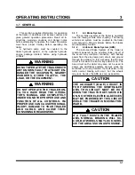
WARNING
DO NOT OPERATE THE TRAILER WITH
ANY KNOWN FAULT THAT MIGHT EN-
DANGER THE OCCUPANTS, NEARBY
WORKERS, OTHER TRAFFIC, THE
LOAD, OR THE EQUIPMENT.
WARNING
DO NOT OPERATE THE TRAILER UN-
TIL YOU HAVE READ THE OPERA-
TOR’S MANUAL AND COMPLETELY
UNDERSTAND THE PROPER USE AND
FUNCTION OF ALL CONTROLS. IM-
PROPER USE CAN CAUSE PERSONAL
INJURY, DAMAGE TO YOUR TRAILER
AND CARGO, AND CAUSE TIME-
CONSUMING BREAKDOWNS.
3-1.1
Air Brake System
The air brake system of the trailer is operated
from the towing vehicle after coupling. The towing
vehicle’s air system must be coupled to the trailer
and charged to 90 psi minimum before the brakes
can adequately function.
3-1.2
Anti-Lock Brake System (ABS)
The Anti-Lock Brake System of the trailer is
constant powered by the auxiliary (blue) circuit of
the seven way electrical connector, with backup
power from the stop lamp (red) circuit, and ground
through the white wire. It is necessary that the blue
circuit is hot when the tractor key switch is on. The
blue circuit on the trailer may also not be used to
power any additional auxiliary devices while the
semitrailer is moving forward. If a fault exists in the
ABS, normal braking will occur, but the wheels
may lock. Service the ABS as soon as possible.
CAUTION
THE AUXILIARY (BLUE) CIRCUIT IS
FOR POWERING THE SEMITRAILER
ABS. THIS CIRCUIT MUST BE HOT
WHEN THE TRACTOR KEY SWITCH IS
ON. NO OTHER ELECTRICAL DEVICES
MAY BE POWERED BY THIS CIRCUIT
WHILE THE TRAILER IS MOVING FOR-
WARD.
CAUTION
IF A FAULT EXISTS IN THE TRAILER
ABS, NORMAL BRAKING WILL OC-
CUR, BUT WHEELS MAY LOCK. SERV-
ICE THE ABS AS SOON AS POSSIBLE.
3-1
Summary of Contents for 345B
Page 3: ...MODEL 345B TRAILER OPERATOR S MANUAL PURCHASED FROM DATE ADDRESS PHONE NO SERIAL NO ...
Page 8: ......
Page 12: ......
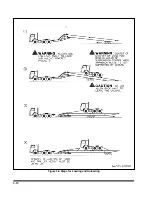
Page 22: ...3 10 Figure 3 4 Steps for Loading and Unloading ...
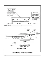
Page 26: ...3 14 Figure 3 7 Rear Impact Guard and Antilock Brake System ...
Page 30: ......
Page 35: ...4 5 Figure 4 2 345B Wiring Diagram ...
Page 36: ...4 6 Figure 4 3 Remote Wiring Diagram ...
Page 41: ...4 11 Figure 4 5 Examples of Camber Figure 4 6 Checking Axle for Bend ...
Page 46: ...4 16 Figure 4 10 Axle and Brake Assembly ...
Page 50: ...4 20 Figure 4 13 Outboard Mount Hub and Drum Figure 4 14 Inboard Mount Hub and Drum ...
Page 54: ...4 24 Figure 4 18 Mounting Tires and Wheels Figure 4 19 Stud Tightening Sequence ...
Page 65: ...5 9 NOTES ...


