3-6.4
The trailer wheels track to the inside of
the towing vehicle during turns. Thus, turning
corners requires a wide swing to prevent
“curb hopping”, and to allow the trailer to
clear any obstacle on the inside of the cor-
ner.
3-6.5
To stop, use a gradual and smooth appli-
cation of brakes.
3-6.6
Backing should be done with care. Tail
overhang, trailer length, and allowable space
must be taken into consideration.
3-6.7
The load on the trailer should be posi-
tioned so a minimum of 8% of the total
weight and a maximum of 30% of the total
weight is on the hitch.
3-7 PARKING THE TRAILER
3-7.1
Position truck/trailer rig on a level, solid
surface.
3-7.2
Set the
PARKING BRAKE
,
not the
trailer hand brake
, and check for proper brake
holding.
3-7.3
Chock wheels of trailer.
3-7.4
Check for any air leaks in lines, relay
valve, brake air chamber, or any other air
system component.
3-8 UNCOUPLING TOWING VEHICLE FROM TRAILER
3-8.1
Park the trailer according to instructions
in
Section 3-7.
3-8.2
Disconnect emergency and service air
lines.
3-8.3
Disconnect the electrical cable and store
so end is not on the ground.
3-8.4
Disconnect safety chains from the tow-
ing vehicle.
3-8.5
Lower the landing gear to the ground.
Tilt trailer bed up so next landing gear pin
hole is available. Install and lock landing
gear pins. Unlock pintle hitch. Tilt trailer bed
down until pintle hitch eye lifts off pintle
hook.
3-8.6
Shut off towing vehicle hydraulic supply,
disconnect hydraulic hoses.
3-8.7
Verify that all service lines and safety
chains are disconnected and trailer wheels
are chocked.
3-8.8
Pull towing vehicle away from the trailer.
3-5
Summary of Contents for 345B
Page 3: ...MODEL 345B TRAILER OPERATOR S MANUAL PURCHASED FROM DATE ADDRESS PHONE NO SERIAL NO ...
Page 8: ......
Page 12: ......
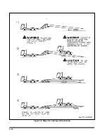
Page 22: ...3 10 Figure 3 4 Steps for Loading and Unloading ...
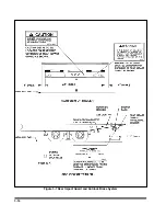
Page 26: ...3 14 Figure 3 7 Rear Impact Guard and Antilock Brake System ...
Page 30: ......
Page 35: ...4 5 Figure 4 2 345B Wiring Diagram ...
Page 36: ...4 6 Figure 4 3 Remote Wiring Diagram ...
Page 41: ...4 11 Figure 4 5 Examples of Camber Figure 4 6 Checking Axle for Bend ...
Page 46: ...4 16 Figure 4 10 Axle and Brake Assembly ...
Page 50: ...4 20 Figure 4 13 Outboard Mount Hub and Drum Figure 4 14 Inboard Mount Hub and Drum ...
Page 54: ...4 24 Figure 4 18 Mounting Tires and Wheels Figure 4 19 Stud Tightening Sequence ...
Page 65: ...5 9 NOTES ...


