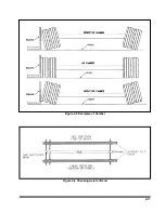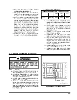
d.
Follow the same procedures as in
Section
except place the axle gauge
above and below the axle. If gauge point gap
is found, the axle has positive or negative
camber. The trailer axle has no camber from
the factory. If it is found to have positive or
negative camber, axle replacement is neces-
sary
(See Figure 4-5
for examples of cam-
ber).
4-7.2
Axle Alignment
Proper axle to pintle eye alignment is neces-
sary to obtain straight tracking. If axle alignment is
off, “dog-tracking” occurs. Check alignment manu-
ally or by using a semitrailer alignment machine. In
either case, a thorough inspection of the complete
suspension must be performed and all defects cor-
rected before aligning.
a. Manual Alignment Procedure
1.
Position semitrailer on a firm and level
surface. Insure that the undercarriage is in
the rear most position. Eliminate any
suspension binding due to sharp turns or
unusual maneuvers.
2.
Detach tractor from the semitrailer and jack
the trailer up sufficiently to permit
measuring from the underside of the trailer.
3.
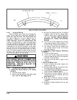
Suspend a plumb bob at axle height from
the center of the pintle eye.
4.
Measure (D) from the plumb bob to the
center point on one end of the axle. Record
this measurement
(See Figure 4-7
5.
Measure (D1) to the other end of the axle in
the same manner as in
Step 4.
. Record this
measurement
(See Figure 4-7).
6.
Set D about 1/8" shorter than D1 to insure
proper trailer tracking on slope of road.
7.
The suspensions must be in good repair
with no binding or other restrictions before
aligning. All defective parts of the
suspension or axles must be replaced
immediately.
b. Air Ride Suspension Axles
The air ride suspension is aligned and ad-
justed at the factory and it should not be necessary
to align the axles. If, however it does become nec-
essary to align the axles, the procedure is as fol-
lows:
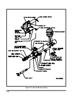
1.
To align air ride suspension axles, locate
the front axle equalizer beam pivot bolt in
front hanger at front end of lock nut. Rotate
the head of the pivot bolt. For axle
alignment forward, rotate bolt head
clockwise. For axle alignment rearward,
rotate the bolt head counter-clockwise.
Loosen the suspension pivot bolt lock nut.
4-12
Figure 4-7 Checking Axle Alignment
Summary of Contents for 345B
Page 3: ...MODEL 345B TRAILER OPERATOR S MANUAL PURCHASED FROM DATE ADDRESS PHONE NO SERIAL NO ...
Page 8: ......
Page 12: ......
Page 22: ...3 10 Figure 3 4 Steps for Loading and Unloading ...
Page 26: ...3 14 Figure 3 7 Rear Impact Guard and Antilock Brake System ...
Page 30: ......
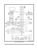
Page 35: ...4 5 Figure 4 2 345B Wiring Diagram ...
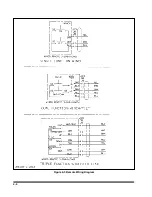
Page 36: ...4 6 Figure 4 3 Remote Wiring Diagram ...
Page 41: ...4 11 Figure 4 5 Examples of Camber Figure 4 6 Checking Axle for Bend ...
Page 46: ...4 16 Figure 4 10 Axle and Brake Assembly ...
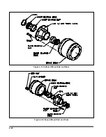
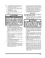
Page 50: ...4 20 Figure 4 13 Outboard Mount Hub and Drum Figure 4 14 Inboard Mount Hub and Drum ...
Page 54: ...4 24 Figure 4 18 Mounting Tires and Wheels Figure 4 19 Stud Tightening Sequence ...
Page 65: ...5 9 NOTES ...


