c.
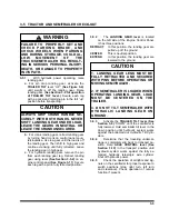
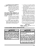
The
20,000 lb and 30,000 lb PNEUMATIC
WINCH CONTROL
has two positions.
RELEASE
In this position, the winch is disen-
gaged and air tension (if present) is
released from the cable. Allow up to
15 seconds for release of air tension.
The cable can then “free-wheel”. The
cable may need to be slackened to
allow winch to disengage.
IMPORTANT
WHEN REELING WINCH, MOMENTARILY RO-
TATE REEL IN OPPOSITE DIRECTION TO RE-
LIEVE TENSION ON WINCH GEARS. THIS WILL
AID IN WINCH RELEASE.
TENSION
In this position, the winch is engaged
and cable can be “power” spooled in
or out. The winch is now controlled
by the Winch Hydraulic Lever. Winch
air tensioner will also be engaged, if
present.
d.
The
20,000 lb WINCH AIR TENSION
or
pressure on the cable is controlled by an air
pressure regulator located behind the main
control panel. It is set at 60 psi but can be ad-
justed, if desired, for more or less tension.
1.
To adjust, turn the regulator adjusting
knob. Clockwise rotation increases and
counterclockwise rotation decreases outlet
pressure and tension.
2.
When reducing from a higher to a lower
setting, first reduce to some pressure less
than that desired, then bring up to the
desired point.
3.
Push lockring on adjusting knob downward
to lock pressure setting. To release, push
lockring upward. Free spool tension is
applied by adjustable spring load on the
cable. Free spool tension can be adjusted,
if desired, for more or less free spool
tension.
e.
The
30,000 lb WINCH AIR TENSION
or
pressure on the cable is controlled at system
air pressure for operation. An air pressure
regulator located behind the main control
panel is used to reduce air pressure and ca-
ble tension during free spool. It is set at 60
psi, but can be adjusted, if desired, for more
or less free spool tension. For adjustment
procedure,
see Section 3-16.2d. 1. through
f.
Once the winch is selected, winch operation
is the same as described in
Section 3-16.1.
IMPORTANT
REMOTE
CONTROL
OPERATION
IS
DE-
SCRIBED IN SECTION 3-21.
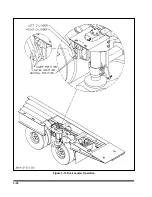
3-17 DOCK LEVELER CONTROL OPERATION (OPTION)
DANGER
WHEN USING DOCK LEVELERS, THE
SEMITRAILER MUST BE KEPT LEVEL
AT ALL TIMES. DO NOT LOWER THE
PARKING STANDS. LOADS BEING
PLACED ON THE SEMITRAILER MUST
BE KEPT CENTERED ON THE SEMI-
TRAILER. AN UNLEVEL SEMITRAILER
MAY ALLOW A LOAD TO SLIDE, CAUS-
ING INJURY OR DEATH TO ANYONE
NEAR THE LOAD!
DANGER
1. DO NOT OPERATE DOCK LEVEL-
ERS WITH UNDERCARRIAGE OUT OF
REAR POCKETS.
2. DO NOT OPERATE DOCK LEVEL-
ERS WITH INSUFFICIENT SPACE ON
BOTH SIDES OF THE SEMITRAILER.
SEMITRAILER WILL LEAN TOWARD
THE SIDE WITH THE SHORTEST CYL-
INDER. PERSONS OR EQUIPMENT
CAN BE CRUSHED BETWEEN SEMI-
TRAILER SIDE AND RIGID OBJECTS.
3. TRACTOR PARK BRAKES MUST BE
SET WHEN USING DOCK LEVELERS.
3-19
Summary of Contents for 600B Series
Page 8: ......
Page 12: ......
Page 14: ...3 2 Figure 3 1 Front Trailer Terminology Figure 3 2 Rear Trailer Terminology...
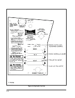
Page 18: ...3 6 Figure 3 4 Hydraulic Controls...
Page 26: ...3 14 Figure 3 7 Steps for Loading and Unloading...
Page 32: ...3 20 Figure 3 10 Dock Leveler Operation...
Page 38: ...3 26 Figure 3 14 Rear Impact Guard and Antilock Brake System...
Page 42: ...4 2 Figure 4 1 Lubrication Points...
Page 48: ...4 8 Figure 4 3 600B Wiring Diagram...
Page 49: ...4 9 Figure 4 4 Remote Wiring Diagram...
Page 52: ...4 12 Figure 4 5 Tandem Axle Air Ride Suspension System Figure 4 6 Air Ride Height Adjustment...
Page 54: ...4 14 Figure 4 7 Triple Axle Air Ride Suspension System...
Page 57: ...4 17 Figure 4 9 Checking Axle Alignment Figure 4 10 Examples of Camber...
Page 61: ...4 21 Figure 4 13 Axle and Brake Assembly...
Page 71: ...4 31 Figure 4 21 Dock Leveler Leg Assembly...
Page 73: ...4 33 Figure 4 22 Crank Landing Gear Assembly...
Page 84: ...NOTES 5 10...

