3-18.3
The
HYDRAULIC POWER SUPPLY
ENGINE CHOKE (See Figure 3-11)
is lo-
cated to the left of the Engine Ignition Switch
on the driver’s side of the semitrailer. The
purpose of the Choke is to aid the starting
procedure.
IN
This is normal operating position.
OUT
Set the choke in this position as an
aid to start the engine. Once the en-
gine is started, push in the choke
fully.
3-18.4
The
HYDRAULIC POWER SUPPLY
ENGINE THROTTLE
is located to the below
the choke on the driver’s side of the semi-
trailer. The Engine Throttle controls the
speed at which the engine operates
(See
Figure 3-11).
It is a variable position control:
FULL OUT
In this position, the engine throttle is
fully open, letting it run at full speed.
FULL IN
In this position, the engine throttle is
closed, letting the engine run at a
slow idle.
3-18.5
To start, pull the choke completely out
and set the throttle to the MEDIUM IDLE po-
sition.
3-18.6
Turn the ignition key to the START po-
sition. The engine should crank and then
start.
CAUTION
DO NOT CRANK ENGINE FOR MORE
THAN 10 SECONDS. IF ENGINE DOES
NOT START, CONSULT THE OWNER’S
MANUAL SUPPLIED WITH THE EN-
GINE.
3-18.7
When the engine starts, release the
key. Gradually push the choke lever in until
the engine runs smoothly.
IMPORTANT
BLACK SMOKE FROM THE EXHAUST AND A
ROUGH ENGINE INDICATE OVERCHOKING.
3-18.8
To adjust the speed, turn the throttle
control in or out, as needed, until the engine
runs smoothly at a speed capable of with-
standing use of the hydraulic controls. The
hydraulic controls should now be functional.
3-18.9
Before shutting it off, allow the engine
to cool down by running at a slow idle for
thirty seconds. Then turn the ignition switch
to the off position.
3-18.10
Once the engine is cool, turn or push
the throttle and choke control completely in
and turn the key to the OFF position.
3-19 AIR RIDE OPERATION
3-19.1
Trailer air pressure must be maintained
above 90 PSI before operating. PROTEC-
TION VALVES are used to maintain 65 PSI
air brake pressure during suspension or re-
mote system air loss.
3-19.2
The Model 660B tandem axle semi-
trailer is equipped with a ride control valve
located on front axle. When moving the un-
dercarriage from transport to load position,
the front axle is raised off ground, causing
suspension air bags to deflate achieving low
load angle.
CAUTION
IF SUSPENSION AIR LOSS SHOULD
OCCUR, COMPLETELY DEFLATE SUS-
PENSION AND TEMPORARILY OPER-
ATE ON THE AIR SPRINGS INTERNAL
RUBBER BUMPERS. CAREFULLY
PROCEED TO THE NEAREST SEMI-
TRAILER SERVICE FACILITY. TO DE-
FLATE THE AIR SUSPENSION, DIS-
CONNECT THE LOWER CONNECTION
ON THE LINKAGE OF THE AUTOMATIC
AIR VALVES. ROTATE THE VALVE
CONTROL ARMS DOWN ABOUT 45
o
TO EXHAUST THE AIR. TO RESTORE
TO NORMAL OPERATION, SIMPLY RE-
VERSE THE PROCEDURE.
3-23
Summary of Contents for 600B Series
Page 8: ......
Page 12: ......
Page 14: ...3 2 Figure 3 1 Front Trailer Terminology Figure 3 2 Rear Trailer Terminology...
Page 18: ...3 6 Figure 3 4 Hydraulic Controls...
Page 26: ...3 14 Figure 3 7 Steps for Loading and Unloading...
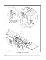
Page 32: ...3 20 Figure 3 10 Dock Leveler Operation...
Page 38: ...3 26 Figure 3 14 Rear Impact Guard and Antilock Brake System...
Page 42: ...4 2 Figure 4 1 Lubrication Points...
Page 48: ...4 8 Figure 4 3 600B Wiring Diagram...
Page 49: ...4 9 Figure 4 4 Remote Wiring Diagram...
Page 52: ...4 12 Figure 4 5 Tandem Axle Air Ride Suspension System Figure 4 6 Air Ride Height Adjustment...
Page 54: ...4 14 Figure 4 7 Triple Axle Air Ride Suspension System...
Page 57: ...4 17 Figure 4 9 Checking Axle Alignment Figure 4 10 Examples of Camber...
Page 61: ...4 21 Figure 4 13 Axle and Brake Assembly...
Page 71: ...4 31 Figure 4 21 Dock Leveler Leg Assembly...
Page 73: ...4 33 Figure 4 22 Crank Landing Gear Assembly...
Page 84: ...NOTES 5 10...


