i.
Lift out polyethylene bushing.
j.
Remove thrust bearing, thrust washer, and
woodruff key from screw in assembly.
k.
Replace all worn, bent, or broken parts.
4-14.4
Leg Assembly
a.
Place thrust washer on top of elevating
screw. Thrust bearing follows and must be as-
sembled with cup of bearing up.
b.
Place outer leg over screw and nut portion
of inner leg assembly. Press down until
threaded part of elevating screw is clearly
visible through hole in top of the outer leg.
c.
Fit polyethylene bushing into place around
screw in leg assembly and push all the way
down into bearing block.
d.
Install woodruff key in slot of elevating
screw and install bevel gear in place.
e.
Secure bevel gear. Use Loc-tite on threads
of screw and install jam lock nut. Make sure
bevel gear turns freely.
f.
Place bevel pinion gear on top of bevel gear
on the opposite side from mounting bracket of
single speed out leg, or mounting bracket side
of 2-speed outer leg.
g.
Install shaft through outer. Install shims re-
moved previously and slide shaft through
shims and bevel pinion gear.
h.
Align holes in bevel pinion gear with hole in
shaft, insert groove pin so that shafts turn
freely and the two gears are engaged prop-
erly.
i.
Check for proper shimming. Proper shim-
ming achieved when the shafts turn freely
and there is no more than 1/16" gap between
the shims and the outer leg when shaft is
pushed toward the bevel gear.
j.
Make sure this assembly is well lubricated
with a permanent type lubricant (1/2 pound,
minimum).
k.
Replace gasket, metal cover, and self tap-
ping screws.
l.
Install landing gear back on trailer. Adjust
both legs to the same length and install cross
shaft and bolts and nuts. When installing
cross shaft make sure there is enough end
play and gears crank freely.
4-14.5
Gearbox Assembly
a.
To replace shifter gear, install pin in shaft.
Then slide shifter on shaft so that recess in
shifter gear fits over pin. Install spiral pin.
b.
Insert shaft with gear in lower hole of gear-
box and install shifter spring in place.
c.
Slide gear on shaft and insert shaft in mid-
dle hole of gear box.
d.
Install step gear on shaft and secure with
spiral pins.
e.
Place idler gear in shaft with shoulder of
gear to inside.
f.
Gears must be coated with permanent type
grease in order to obtain successful opera-
tion.
g.
Replace gasket and gearbox cover and as-
semble with bolts and nuts.
4-34
Summary of Contents for 600B Series
Page 8: ......
Page 12: ......
Page 14: ...3 2 Figure 3 1 Front Trailer Terminology Figure 3 2 Rear Trailer Terminology...
Page 18: ...3 6 Figure 3 4 Hydraulic Controls...
Page 26: ...3 14 Figure 3 7 Steps for Loading and Unloading...
Page 32: ...3 20 Figure 3 10 Dock Leveler Operation...
Page 38: ...3 26 Figure 3 14 Rear Impact Guard and Antilock Brake System...
Page 42: ...4 2 Figure 4 1 Lubrication Points...
Page 48: ...4 8 Figure 4 3 600B Wiring Diagram...
Page 49: ...4 9 Figure 4 4 Remote Wiring Diagram...
Page 52: ...4 12 Figure 4 5 Tandem Axle Air Ride Suspension System Figure 4 6 Air Ride Height Adjustment...
Page 54: ...4 14 Figure 4 7 Triple Axle Air Ride Suspension System...
Page 57: ...4 17 Figure 4 9 Checking Axle Alignment Figure 4 10 Examples of Camber...
Page 61: ...4 21 Figure 4 13 Axle and Brake Assembly...
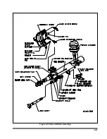
Page 71: ...4 31 Figure 4 21 Dock Leveler Leg Assembly...
Page 73: ...4 33 Figure 4 22 Crank Landing Gear Assembly...
Page 84: ...NOTES 5 10...


