background image

3

OPERATION AND MAINTENANCE

3-1

SAFETY INFORMATION AND DECAL LOCATIONS

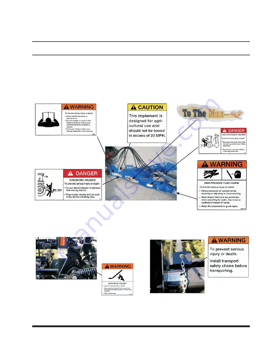
The types of Safety/Information Signs and lo-

cations on the harrow are shown in

Figures 3-1,

3-2, and 3-3

. Good safety practice requires that

you familiarize yourself with the various Safety/In-
formation Signs. Replacement part numbers are
found in the Parts List manual. Immediately replace
all worn, damaged, peeling, or obscured decals.

3-1

hitch frame decals

Figure 3-1 Hitch Frame Decals

side wing decals

Figure 3-2 Side Wing Decals

wing frame decals

Figure 3-3 Wing Frame Decals

Summary of Contents for 7130 TO THE MAX

Page 1: ...MODEL 7130 TO THE MAX ROLLER HARROW OPERATOR S MANUAL 1900 NORTH STREET MARYSVILLE KANSAS 66508 785 562 5381 F 452 1007 10 07 Roller Harrow...

Page 2: ......

Page 3: ...MODEL 7130 TO THE MAX ROLLER HARROW OPERATOR S MANUAL PURCHASED FROM DATE ADDRESS PHONE NO SERIAL NO i...

Page 4: ...NOTES ii...

Page 5: ...AL MAINTENANCE SAFETY 3 4 3 6 TIRE SAFETY 3 5 3 7 PRE OPERATION SET UP 3 6 3 8 HOOKING THE HARROW TO THE TRACTOR 3 6 3 9 PUTTING THE HARROW INTO THE FIELD 3 8 3 10 GENERAL OPERATING TIPS 3 9 3 11 HARR...

Page 6: ...IF NOT AVOIDED WILL RESULT IN DEATH OR SERIOUS INJURY WARNING WARNING INDICATES A POTENTIALLY HAZARDOUS SITUA TION WHICH IF NOT AVOIDED COULD RESULT IN DEATH OR SERIOUS INJURY CAUTION CAUTION INDICAT...

Page 7: ...t NOTE IF THE EQUIPMENT IS IMPROPERLY ASSEMBLED OR MAINTAINED THE WARRANTY IS VOID IF YOU HAVE ANY QUESTIONS CONTACT LANDOLL CORPORATION 1900 NORTH STREET MARYSVILLE KANSAS 66508 or phone 785 562 5381...

Page 8: ...NOTES 1 2...

Page 9: ...ds up 14 6 w boards down 11 11 Overall Weight 13 600 lbs Power Requirements 200 hp in most conditions Rolling Blades 17 dia reel w hardened steel blades on a spring cushioned frame Rotary Harrow Tines...

Page 10: ...65 81 90 112 9 16 12 55 62 80 100 110 137 9 16 18 60 75 90 112 130 162 5 8 11 75 94 110 137 170 212 5 8 18 85 106 130 162 180 225 3 4 10 130 162 200 250 280 350 3 4 16 150 188 220 275 320 400 7 8 9 12...

Page 11: ...146 75 85 16 115 125 202 218 109 121 20 160 180 248 272 213 237 24 185 215 303 327 238 262 32 250 290 310 340 LANDOLL CORPORATION HYDRAULIC FITTING TORQUE SPECIFICATIONS 37o JIC ORS ORB REV 10 97 THIS...

Page 12: ......

Page 13: ...3 Good safety practice requires that you familiarize yourself with the various Safety In formation Signs Replacement part numbers are found in the Parts List manual Immediately replace all worn damage...

Page 14: ...ng assemblies Replace any suspect parts to prevent accidents 3 3 OPERATIONAL SAFETY When this equipment is operated in populated areas extreme care must be taken If anyone comes within several hundred...

Page 15: ...pulling the harrow Always take precautions near overhead wires 3 4 2 Extremity Wing Lights The harrow comes equipped with back wing lights that work in conjunction with the flashing signal tractor li...

Page 16: ...r pressure can penetrate the skin Openings in the skin and minor cuts are susceptible to infection from hydraulic fluid If injured by escaping hydraulic fluid see a doctor at once Gangrene can result...

Page 17: ...ience to do the job Follow recommended tire pressures in Table 3 6 on page 3 20 Always order and install tires and wheels with appropriate capacity to meet or exceed the weight of the transport cart a...

Page 18: ...R 3 8 1 The harrow comes equipped with a clevis style bolt on cast hitch The clevis por tion must be removed if your tractor is equipped with a double tongue on the drawbar If your tractor has a singl...

Page 19: ...he cast hitch up or down to a location on the hitch plate where the frame will be level c Rebolt the cast hitch in place d Hitch height can vary depending on the de sired pressure on leveling boards 3...

Page 20: ...e raised position See Figure 3 12 IMPORTANT DAMAGE TO COVER BOARD WILL RESULT IF YOU FAIL TO FOLLOW THIS PROCEDURE d Slowly unfold the wings Once wings are completely unfolded set wing valve to the FL...

Page 21: ...olume of residue increases cover board tension will need to be relaxed to allow proper flow of residue Failure to decrease tension will re sult in bunching of stalks and trash the infa mous rabbit hut...

Page 22: ...f the main gear spindle mount See Figure 3 18 Raise the pin positions to lower the wheels to work shallower Lower the pin positions to raise the wheels to work deeper See Figure 3 19 Replace both pins...

Page 23: ...ng depth slide arms down to raise outside wings IMPORTANT THERE ARE TWO PIN HOLE LOCATIONS WHICH ALLOW HALF HOLE INCREMENTS WHEN RAISING OR LOWERING THE OUTER GAUGE WHEELS EACH HALF HOLE ON THE OUTER...

Page 24: ...s the width of the harrow au tomatically compensating for ridges or de pressions in the terrain If a cover board hits a rock or obstruction it will float up and return to its down position b The facto...

Page 25: ...ting the cover boards will rest lightly on the ground At the maximum pressure the cover boards will exert enough down force to lift the rear of the harrow frame IMPORTANT DURING A TURN IT IS COMMON FO...

Page 26: ...over board angle by changing turnbuckle or reducing psi Not Filling in Valleys Increase psi or adjust gauge wheels to deeper setting to create more loose soil to mix with the residue Streaking of Resi...

Page 27: ...AGE TO THE FRAME IMPORTANT RUNNING THE TOOLS TOO LOOSE MAY CAUSE POOR PERFORMANCE AND ACCEL ERATED WEAR ON THE BEARINGS U BOLTS INDIVIDUAL TOOLS AND OR COVER BOARDS a When hanging in transport positi...

Page 28: ...ve socket or air wrench to make these changes IMPORTANT WHEN TIGHTENING COMPRESS SPRING UNTIL INSIDE SPACER BOTTOMS OUT 3 15 4 Firmly retighten the inside locking nut to hold adjustment IMPORTANT THE...

Page 29: ...check all bearings and u bolts for damage or wear 3 16 1 Daily Every 10 hours a Wing hinges 4 See Figure 3 29 b Chopper reel bearing housings outer 6 1 pump of grease only See Figure 3 30 c Chopper r...

Page 30: ...e 2 See Figure 3 33 b Hitch pivot point 2 See Figure 3 34 c Turnbuckle adjustment 2 penetrating oil only See Figure 3 35 3 18 Figure 3 33 Main Frame Hinge 2 Figure 3 34 Hitch Pivot Point 2 Figure 3 35...

Page 31: ...3 16 3 Seasonally Every 200 hours a Wheel bearings 6 See Figure 3 36 b Back hinge point 2 See Figure 3 37 3 19 Figure 3 36 Wheel Bearings 6 Figure 3 37 Back Hinge Point 2 Penetrating Oil Only...

Page 32: ...litary Specifications MIL G 10924C 3 17 2 General Purpose Grease Make sure to use grease that fits your ex pected air temperature range during operation in tervals SAE Multipurpose Grease or SAE Multi...

Page 33: ...NOTES 3 21...

Page 34: ......

Page 35: ...oo slow reduce tension on leveling board spring Remove latch assembly from leveling board arms and let leveling boards float THE MODULE CHAINS ARE LOPING Too fast or too loose slow down by 1 mph incre...

Page 36: ...90 degree angles to better level the field Improper adjustment of leveling boards increase tension on leveling boards Ground is too hard for proper harrow operation if possible work all ground before...

Page 37: ...NOTES 4 3...

Page 38: ......

Page 39: ...l 7130 Series To The Max TM Roller Harrow Operator s Manual Re Order Part Number F 452 1007 LANDOLL CORPORATION 1900 North Street Marysville Kansas 66508 785 562 5381 800 428 5655 WWW LANDOLL COM F 45...

Reviews: