3-7 PARKING THE TRAILER
3-7.1
Position truck/semitrailer rig on a level,
solid surface.
3-7.2
Set the
PARKING BRAKE
,
not the
semitrailer hand brake
, and check for proper
brake holding.
3-7.3
Chock wheels of semitrailer.
3-7.4
Check for any air leaks in lines, relay
valve, brake pods, or any other air system
component.
WARNING
WHEN LEAVING THE SEMITRAILER
UNATTENDED, POSITION ALL HY-
DRAULIC CONTROLS TO THE NEU-
TRAL OR “OFF” POSITION OR DIS-
CONNECT THE TRACTOR HYDRAULIC
HOOK-UP.
3-8 UNCOUPLING TOWING VEHICLE FROM SEMITRAILER
3-8.1
Park the semitrailer according to instruc-
tions in
Section 3-7.
3-8.2
Disconnect the emergency and service
air lines and attach them to the tractor glad-
hand holders. If present, install dummy glad-
hands on trailer couplings.
3-8.3
Disconnect the 7-pole cable and hydrau-
lic lines from the semitrailer and store with
the tractor.
3-8.4
Pull the tractor fifth wheel plate latch re-
lease lever.
3-8.5
Attempt to pull the tractor forward. If the
tractor uncouples, verify all service lines are
disconnected and semitrailer wheels are
chocked. If tractor does not disconnect, re-
peat
3-8.6
Pull the tractor away from the semi-
trailer.
DANGER
ALWAYS CHECK BEHIND AND UNDER
THE TRUCK AND SEMITRAILER FOR
PERSONS OR OBJECTS BEFORE
MOVING. FAILURE TO CHECK CAN
LEAD TO SERIOUS PERSONAL IN-
JURY OR DEATH TO OTHERS, OR
DAMAGE TO PROPERTY.
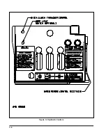
3-9 TRAILER LIFT LEVER
The
TRAILER LIFT lever (See Figures 3-1
and 3-3)
is located on the driver’s side of the
gooseneck assembly. It is the middle lever and has
three positions:
UP
This position raises the semitrailer
deck, allowing the load blocks to be
lowered into transport position.
CENTER
This is the neutral position. The
semitrailer stays in its current posi-
tion.
DOWN
This position lowers the semitrailer
deck to the ground, allowing the de-
tachment of the gooseneck or allow-
ing the weight of the semitrailer deck
and load to rest on the load blocks.
Also, this lowers the gooseneck lift
arms, permitting the transport of the
detached gooseneck.
3-8
Summary of Contents for 825A
Page 8: ......
Page 12: ......
Page 14: ...3 2 Figure 3 1 Model 825 Trailer Terminology Figure 3 2 Service Hookups...
Page 18: ...3 6 Figure 3 3 Hydraulic Controls...
Page 22: ...3 10 Figure 3 5 Swingout Outrigger Platform Extension...
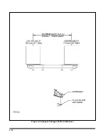
Page 24: ...3 12 Figure 3 6 Gooseneck Attachment to Frame...
Page 34: ......
Page 36: ...4 2 Figure 4 1 Lubrication Points...
Page 40: ...4 6 Figure 4 2 Model 825A Wiring Diagram...
Page 43: ...4 9 Figure 4 4 Tandem Axle Air Ride Suspension System...
Page 44: ...4 10 Figure 4 5 Tandem Axle W Flip Air Ride Suspension System...
Page 47: ...4 13 Figure 4 8 Checking Axle Alignment Figure 4 9 Examples of Camber...
Page 52: ...4 18 Figure 4 12 Axle and Brake Assembly...
Page 59: ...4 25 Figure 4 18 Mounting Tires and Wheels Figure 4 19 Stud Tightening Sequence...
Page 69: ...NOTES 5 9...
Page 70: ......


