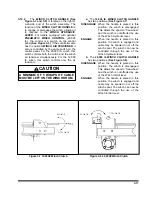
3-12 PREPARATION FOR LOADING AND UNLOADING
CAUTION
TANDEM AXLE SEMITRAILER MAXI-
MUM CONCENTRATED LOAD IN A 16
FT. AREA IS 50,000 LBS.
WARNING
1. THE SEMITRAILER MUST BE COU-
PLED TO A TRACTOR.
2. BEFORE OPERATING:
DO NOT EXCEED THE GROSS AXLE
WEIGHT RATINGS FOR ANY AXLE ON
YOUR VEHICLE. THE COMBINED
WEIGHT OF THE SEMITRAILER AND
CARGO MUST NO EXCEED THE
GROSS VEHICLE WEIGHT RATING
(GVWR) OF THE TRAILER.
DANGER
BE SURE TO KEEP FEET AND ALL
OTHER PARTS OF YOUR BODY
CLEAR OF THE BOTTOM OF THE
SEMITRAILER DURING LOWERING
OPERATION. FAILURE TO KEEP YOUR
FEET OR BODY CLEAR MAY RESULT
IN SERIOUS PERSONAL INJURY OR
DEATH.
3-12.1
Practice all standard industrial safety
standards. Do not load any payload that will
overload any component of the trailer or
cause an unsafe condition.
3-12.2
Park the tractor/semitrailer in a straight
line on level even surface. Set the tractor
brakes and release the semitrailer brakes
(See Figure 3-6)
.
3-12.3
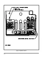
Start operation of hydraulic power sys-
tem.
3-12.4
Move
TRAILER LIFT lever
to the up
position, raising the semitrailer.
3-12.5
Push
LOAD BLOCK RELEASE BUT-
TON
raising the load blocks up.
3-12.6
Push carrier lock release button to allow
carrier to rotate when activating
TRAILER
LIFT lever
.
3-12.7
Continue to push
RELEASE BUTTONS
while moving
TRAILER LIFT lever
to the
down position, lowering the semitrailer to the
ground.
3-12.8
Continue with
TRAILER LIFT lever
in
the down position until the gooseneck lif-
tarms rest on the tractor frame rails. A clear-
ance of 1/8 to 1/4 inch should be obtained
between the gooseneck load hooks and the
frame receiver hooks.
3-12.9
Disconnect the air and electrical service
lines from the semitrailer to the gooseneck
and store in the storage compartment pro-
vided in the driver’s side approach plate.
3-12.10
Pull the tractor forward a few inches
and determine that the gooseneck has de-
tached from the semitrailer. If the gooseneck
does not detach from the semitrailer, repeat
When gooseneck
does detach from trailer, proceed to pull the
tractor away from the semitrailer.
3-13
Summary of Contents for 825A
Page 8: ......
Page 12: ......
Page 14: ...3 2 Figure 3 1 Model 825 Trailer Terminology Figure 3 2 Service Hookups...
Page 18: ...3 6 Figure 3 3 Hydraulic Controls...
Page 22: ...3 10 Figure 3 5 Swingout Outrigger Platform Extension...
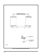
Page 24: ...3 12 Figure 3 6 Gooseneck Attachment to Frame...
Page 34: ......
Page 36: ...4 2 Figure 4 1 Lubrication Points...
Page 40: ...4 6 Figure 4 2 Model 825A Wiring Diagram...
Page 43: ...4 9 Figure 4 4 Tandem Axle Air Ride Suspension System...
Page 44: ...4 10 Figure 4 5 Tandem Axle W Flip Air Ride Suspension System...
Page 47: ...4 13 Figure 4 8 Checking Axle Alignment Figure 4 9 Examples of Camber...
Page 52: ...4 18 Figure 4 12 Axle and Brake Assembly...
Page 59: ...4 25 Figure 4 18 Mounting Tires and Wheels Figure 4 19 Stud Tightening Sequence...
Page 69: ...NOTES 5 9...
Page 70: ......


