3-18.2
The
WINCH CLUTCH HANDLE (See
is located on the right or
curb-side end of the winch assembly. The
function of the
WINCH CLUTCH HANDLE
is
to engage or disengage the winch, allowing it
to respond to the
WINCH HYDRAULIC
LEVER
. For trailers equipped with optional
PNEUMATIC WINCH CONTROL
(20,000
lb.), the control is a switch on the control
panel
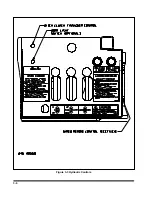
(See Figure 3-3)
. If the semitrailer also
has the optional
WINCH AIR TENSIONER
, it
also is controlled by the same switch on the
control panel. For the 20,000 lb. winch, this
switch controls both the clutch and the winch
air tensioner simultaneously. For the 12,000
lb. winch, this switch controls only the air
tensioner.
CAUTION
A MINIMUM OF 5 WRAPS OF CABLE
MUST BE LEFT ON THE WINCH DRUM.
a.
The
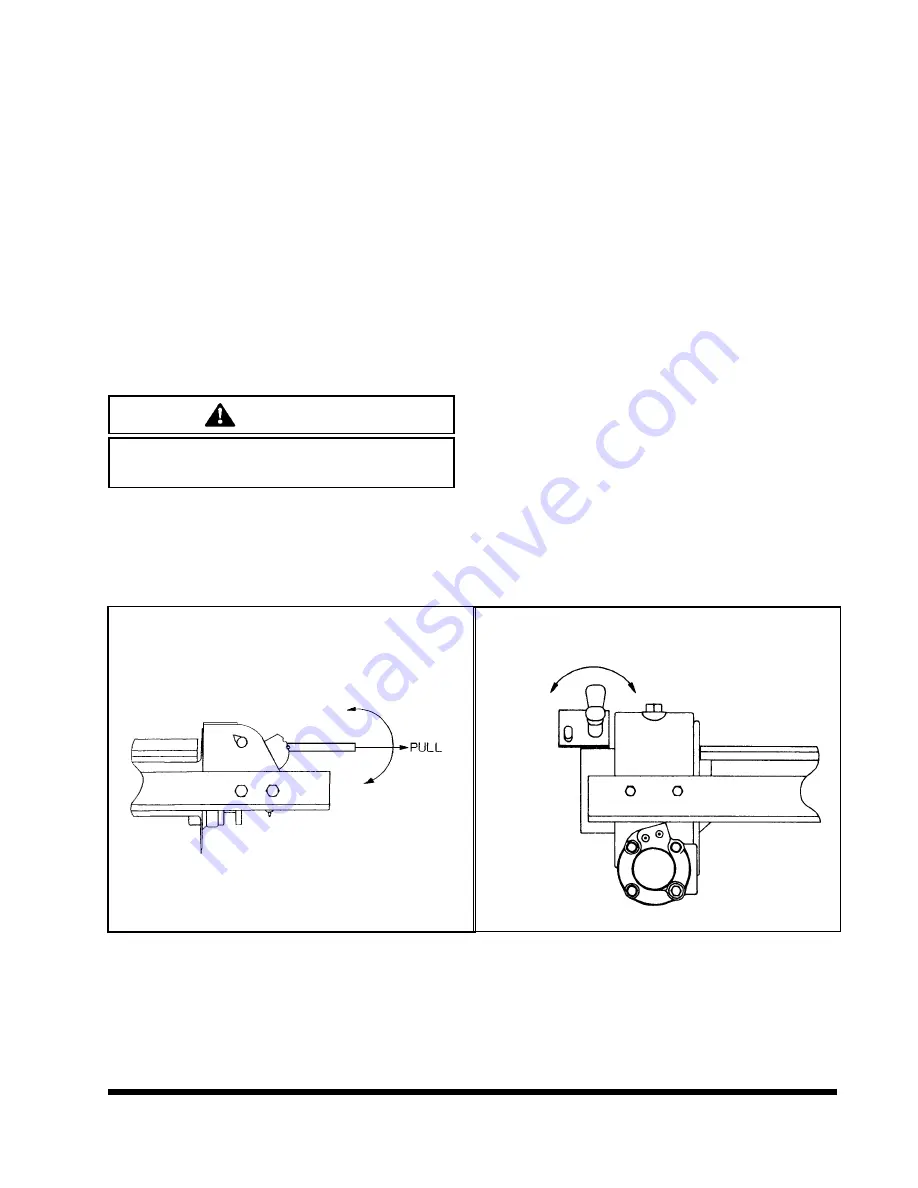
12,000 lb. WINCH CLUTCH HANDLE
has two positions:
(See Figure 3-7)
DISENGAGE
When the handle is placed is this
position, the winch is disengaged.
This allows the spool to “free-wheel”
and the winch is not affected by use
of the Winch Hydraulic lever.
ENGAGE
When the handle is placed in this
position, the winch is engaged and
cable may be spooled on or off the
winch spool. The winch can now be
controlled through the use of the
Winch Hydraulic lever.
b.
The
20,000 lb WINCH CLUTCH HANDLE
has two positions.
(See Figure 3-8).
DISENGAGE
When the handle is placed in this
position, the winch is disengaged.
This allows the spool to “free-wheel”
and the winch is not affected by use
of the Winch In/Out lever.
ENGAGE
When the handle is placed in this
position, the winch is engaged and
cable may be spooled on or off the
winch spool. The winch can now be
controlled through the use of the
Winch In/Out lever.
3-17
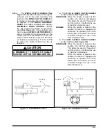
Figure 3-7 12,000# Winch Clutch
DISENGAGE
ENGAGE
Figure 3-8 20,000# Winch Clutch
ENGAGE
DISENGAGE
Summary of Contents for 825A
Page 8: ......
Page 12: ......
Page 14: ...3 2 Figure 3 1 Model 825 Trailer Terminology Figure 3 2 Service Hookups...
Page 18: ...3 6 Figure 3 3 Hydraulic Controls...
Page 22: ...3 10 Figure 3 5 Swingout Outrigger Platform Extension...
Page 24: ...3 12 Figure 3 6 Gooseneck Attachment to Frame...
Page 34: ......
Page 36: ...4 2 Figure 4 1 Lubrication Points...
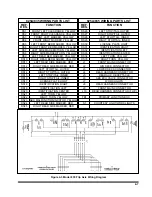
Page 40: ...4 6 Figure 4 2 Model 825A Wiring Diagram...
Page 43: ...4 9 Figure 4 4 Tandem Axle Air Ride Suspension System...
Page 44: ...4 10 Figure 4 5 Tandem Axle W Flip Air Ride Suspension System...
Page 47: ...4 13 Figure 4 8 Checking Axle Alignment Figure 4 9 Examples of Camber...
Page 52: ...4 18 Figure 4 12 Axle and Brake Assembly...
Page 59: ...4 25 Figure 4 18 Mounting Tires and Wheels Figure 4 19 Stud Tightening Sequence...
Page 69: ...NOTES 5 9...
Page 70: ......


