background image

5-6

F-916-0217 Edition

TROUBLESHOOTING GUIDE

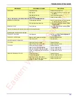
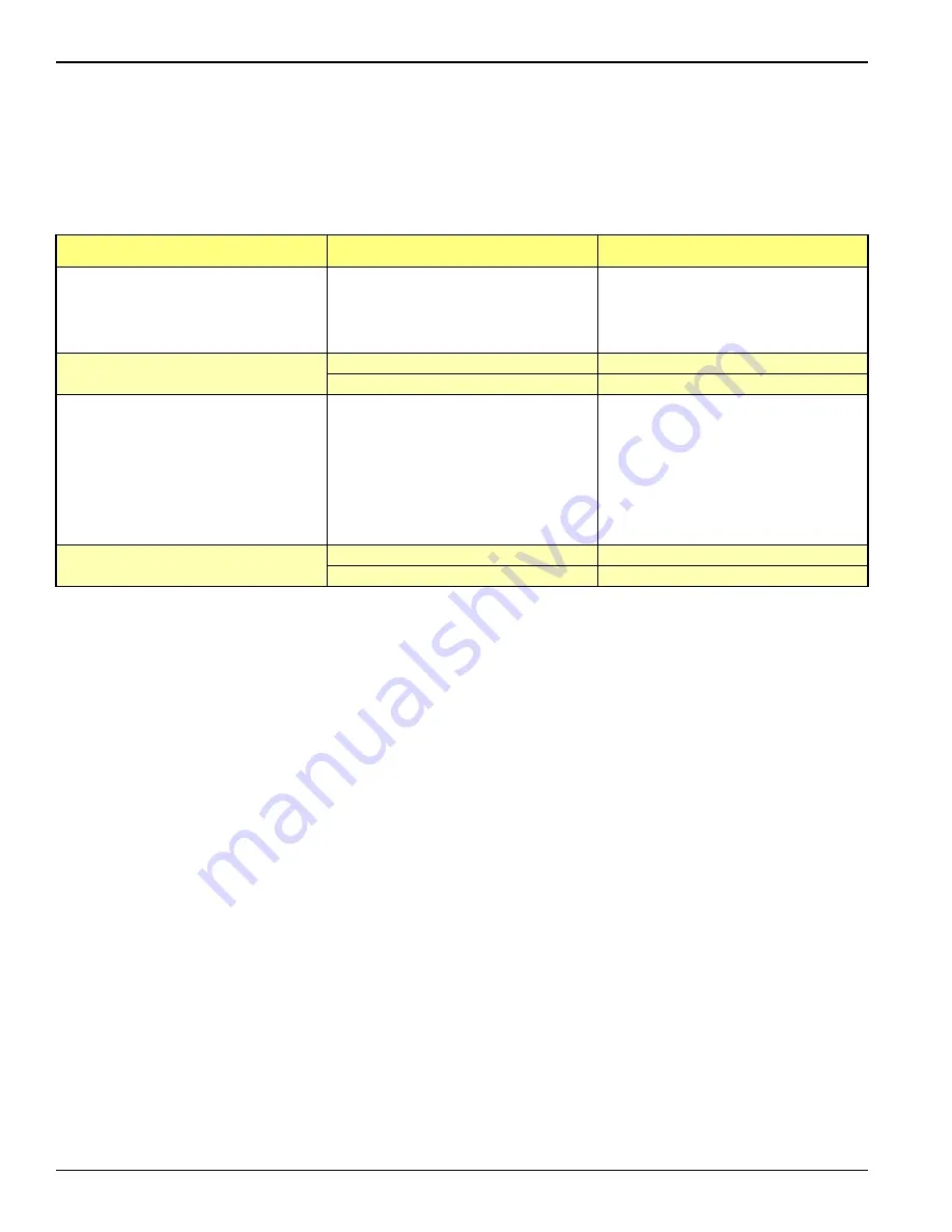
Brake Drums

For maintenance procedures, refer the following 
sections:

• “Suspension Maintenance” on page 4-8
• “Alignment” on page 4-12
• “Brake System Maintenance” on page 4-15
• “Hub and Drum Maintenance” on page 4-21
• “Wheel Bearing Lubrication and Adjustment” on 

page 4-23

PROBLEM

PROBABLE CAUSE

SOLUTION

EXCESSIVE LOSS OF BRAKES OR 
FADING

Overheated brake drums

Check for defective or misadjusted brake 

linings, distorted or over-machined 
drums. Also check for operating 
conditions or loads that create severe 
or excessive brake applications.

BRAKES PULL TO EITHER SIDE

Drums of different diameters

Replace with drums of same diameter.

Foreign matter in drums

Clean drums out.

ROUGH OR NOISY BRAKING ACTION

Defective drums

Pull drums and inspect for any of the 

following; Heat spotted drums, grease 
spotting, blue drums, scored drums, 
excessive wear at rivet holes or edges, 
polished drums, out of round drums, 
unbalanced drums, worn/damaged 
brake components, foreign matter in 
drums. Correct situation or replace 
defective part(s).

VIBRATION IN RIDE

Defective drums or out-of-round

Replace drums.

Out-of-balance drums

Balance drums.

Ea

st

ern

 W

re

cke

r Sa

le

In

c

Summary of Contents for 855E Series

Page 1: ...7 LANDOLL CORPORATION 1900 North Street Marysville Kansas 66508 785 562 5381 800 428 5655 WWW LANDOLL COM Model 855E 855E HD Series Detachable Semitrailer Operator s Manual E a s t e r n W r e c k e r...

Page 2: ...E a s t e r n W r e c k e r S a l e s I n c...

Page 3: ...or to the Semitrailer 3 4 Connecting Tractor Services to the Semitrailer 3 4 Tractor and Semitrailer Check Out 3 5 Towing the Semitrailer 3 6 Parking the Trailer 3 7 Uncoupling Towing Vehicle from Sem...

Page 4: ...ring 4 15 Removal 4 16 Installation 4 16 Emergency Relay Valve Maintenance 4 16 Brake Assembly Maintenance 4 16 Brake Adjustment 4 17 Disassembly for 16 1 2 x 7 Brakes 4 17 Reassembly for 16 1 2 x 7 B...

Page 5: ...e Improper maintenance will void your warranty IF YOU HAVE ANY QUESTIONS CONTACT LANDOLL CORPORATION 1900 NORTH STREET MARYSVILLE KANSAS 66508 PHONE 785 562 5381 or 800 428 5655 OR FAX 888 527 3909 CH...

Page 6: ...you read and understand the information contained in this manual and on the machine signs decals before you attempt to operate or maintain this vehicle The safety statements contained in this manual...

Page 7: ...AL HOOKUP 7 Way Connector AIR HOOKUP Color Coded Gland Hands LOADED DECK HEIGHT 19 1 2 LOAD GROUND CLEARANCE 6 1 2 SWING CLEARANCE 10 9 Gooseneck 90 12 5 Gooseneck dual swing 108 90 CAPACITY FRAME CAP...

Page 8: ...3 4 35 FT LBS WHEEL FASTENERS OUTER SPINDLE NUTS 250 400 FT LBS PILOT WHEEL NUTS 450 500 FT LBS NOTE Capacity ratings are frame capacities only Actual load capacities may be restricted by factors suc...

Page 9: ...110 137 9 16 18 60 75 90 112 130 162 5 8 11 75 94 110 137 170 212 5 8 18 85 106 130 162 180 225 3 4 10 130 162 200 250 280 350 3 4 16 150 188 220 275 320 400 7 8 9 125 156 320 400 460 575 7 8 14 140 1...

Page 10: ...ws Use value in if using prevailing torque nuts Parker Brand Fittings Dash Size 37 Degree JIC O Ring ORS O Ring Boss ORB 4 11 13 15 17 13 15 5 14 16 21 23 6 20 22 34 36 25 29 8 43 47 58 62 40 44 10 55...

Page 11: ...hrough the white wire It is necessary that the blue circuit is hot when the tractor key switch is on The blue circuit on the trailer may not be used to power any additional auxiliary devices while the...

Page 12: ...5 5 803 5 5 5 6 2 5 237 21 7 1 5 0 5 7851 0 35 6685 5 8 283 1 6 7 50 2 2 2 55 5 55 5 2 5217 2 5 226 1 2 22 6 5 0 5 9 5 22 66 29 5 5 8 31 80 7 9 9 6 5 75 6725 203 570 17 6 1 287 2875 56 237 21 7 5 6 2...

Page 13: ...lic lines or start the semitrailer hydraulic power engine Use the TRAILER LIFT lever to raise or lower the kingpin plate sufficiently to set proper coupling height See Trailer Lift Lever on page 3 7 D...

Page 14: ...Keep brakes engaged for remainder of hookup checkout procedures and parking Connecting Tractor Services to the Semitrailer 1 Connect the towing vehicle 7 pole electrical plug to the electrical recepta...

Page 15: ...defect before transporting 7 Check the oil in each hub for proper level and freedom from contamination If hubs are contaminated with water dirt or some other foreign material clean before transporting...

Page 16: ...s 4 mph If the warning lamp does not go off a fault exists in the semitrailer ABS Once the vehicle speed exceeds 4 mph the light should remain off unless a fault occurs or the keyswitch is turned off...

Page 17: ...eat steps 4 and 5 6 Pull the tractor away from the semitrailer DANGER Trailer Lift Lever The TRAILER LIFT lever is located on the driver s side of the gooseneck assembly See Figures 3 1 and 3 3 It is...

Page 18: ...3 8 F 916 0217 Edition OPERATING INSTRUCTIONS Figure 3 3 Hydraulic Controls F K G FRQWUROV E a s t e r n W r e c k e r S a l e s I n c...

Page 19: ...extension is not locked in place Inspect all extensions to insure each is locked securely in position 1 Top of extension planks must be flush with main deck boards 2 Centerline of tracks or tires must...

Page 20: ...ition OPERATING INSTRUCTIONS Figure 3 4 Swing Out Outrigger Platform Extension 2875 5 2 5 0 17 5217 2875 5 0 080 7 127 72 75 5 7 17 5 1 2 75 6 25 7 5 6 17 5 1 2 75 6 25 7 5 6 E a s t e r n W r e c k e...

Page 21: ...ntinue to push the CARRIER LOCK RELEASE BUTTON and TRAILER LIFT lever to down position until the carrier lock goes past the carrier lock stop The release buttons will not need to be pushed after they...

Page 22: ...3 12 F 916 0217 Edition OPERATING INSTRUCTIONS Figure 3 5 Gooseneck Attachment to Frame 226 1 5 0 E a s t e r n W r e c k e r S a l e s I n c...

Page 23: ...ly tied to the deck front and rear using the D rings on the semitrailer frame The load must be tied with chain or ratchet straps sufficient to withstand the weight of the load using standard approved...

Page 24: ...es to their respective gladhand on the side of the gooseneck DANGER CAUTION Unloading the Semitrailer 1 Prepare to unload the semitrailer by following the steps outlined in Preparation for Loading and...

Page 25: ...ectrical devices while the semitrailer is moving forward However additional devices such as remote controls may be powered from the auxiliary circuit while the semitrailer is stationary Back up power...

Page 26: ...5 Periodically check drain holes in the bottom of the relay valve for trailers with air brakes and storage compartments They must be open at all times to avoid moisture entrapment Hot Weather Operati...

Page 27: ...the tractor or trailer 2 Use the Troubleshooting Guide on page 5 1 to check for SYMPTOMS and PROBLEMS of any trailer system not functioning correctly or where wear distortion or breakage are found Ad...

Page 28: ...TION Figure 4 1 Lubrication Points 1 of 2 Figure 4 2 Lubrication Points 2 of 2 1 5 1 86 1 6 285 3 6 2 2 3 9276 7 2 3 6 8 2 27 6 6 55 5 3 927 7 2 3 6 1 3 1 3 7 175 5 6 6 67 0 2 7 21 06 7 86 1 6 6 867 5...

Page 29: ...600XP100 6 ALL YEAR Beacon EP Mobilux EP Mulitiplex Red Multifak EP Alvania EP 7 ALL YEAR Teresstic 32 DTE Light Condor 32 or Magnus 32 Regal Oil R O 32 Turbo T 32 8 ALL YEAR Gear Oil GX SAE 80W 90 M...

Page 30: ...c WARN 20K 30K PLANETARY WINCH GEAR CASE I I 3 c DP 12K 15K 20K 30K WINCH GEAR CASE I I 4 c BRADEN 12K 20K WINCH GEAR CASE I I 5 c WARN 12K PLANETARY WINCH CABLE ASSY I I L 7 c h WARN 20K 30K PLANETAR...

Page 31: ...ERVICE PRECLEANER ELEMENT X SERVICE AIR CLEANER ELEMENT X CHANGE OIL X CHECK SPARK PLUG CONDITION AND GAP X REMOVE COOLING SHROUDS AND CLEAN COOLING AREAS X CHANGE OIL FILTER X NOTES PERFORM THESE MAI...

Page 32: ...the trailer Rinse degreasing solution off with cold water 3 Inspect semitrailer for cause of any reported troubles WARNING 4 Scrape sand prime and repaint areas where finish is missing or where there...

Page 33: ...f a valve or line leaks it should be replaced immediately 3 Check the engine oil each time before using Oil level should be maintained between the ADD and FULL marks on the oil dip stick For further m...

Page 34: ...ue required if bolt head designated with Holland Neway 2 Check all other suspension components for any sign of damage looseness wear or cracks 3 With trailer on level surface and air pressure in exces...

Page 35: ...0 66 0 5 2 5 77 1 1 21 78 1 5 81 21 7 77 1 5 7 1 3257 7 6 9 9 6 7 1 21 78 1 1 21 78 1 5 77 1 5 77 1 5 77 1 0 5 283 5 5 3527 725 9 9 7 21752 9 9 287 72 5 6 1 520 5 6833 1 21 78 1 1 21 78 1 1 21 78 1 1...

Page 36: ...ND LUBRICATION Figure 4 4 Triple Axle w Flip Air Ride Suspension System WULSOH Z IOLS DLU ULGH 3 66 0 5 0 66 0 5 5 77 1 1 21 78 1 7 5 77 1 5 77 1 1 25 283 1 5 77 1 25 5 26 5 8 211 725 0 5 283 5 E a s...

Page 37: ...adjusting lock nut located on the adjusting block allowing the control arm to move approximately 1 inch Move the adjusting block until holes align then insert locating pin See Figure 4 5 7 Align the c...

Page 38: ...and outer wheel bearing surfaces of the spindle being checked and the other point on the inner bearing surface on the other spindle See Figure 4 6 3 Move the axle gauge and place against the back side...

Page 39: ...MAINTENANCE AND LUBRICATION 4 13 Figure 4 6 Checking Axle for Bend Figure 4 7 Examples of Camber E a s t e r n W r e c k e r S a l e s I n c...

Page 40: ...necessary to align the axles If however it does become necessary to align the axles the procedure is as follows 1 To align air ride suspension axles locate the front axle equalizer beam pivot bolt in...

Page 41: ...ne yoke pin for wear and replace as necessary The spring chamber should not be serviced Replace entire unit both service and spring chamber if spring chamber becomes faulty WARNING Caging the Power Sp...

Page 42: ...he emergency line is on the spring brake port 5 Check for leakage by charging the air system to a minimum of 90 psi and applying soap suds to the brake chamber and connections If a growing bubble is d...

Page 43: ...onents servicing as necessary Reassembly for 16 1 2 x 7 Brakes 1 Install new anchor pin bushings camshaft bushing and camshaft seals into the spider See Figure 4 11 IMPORTANT When installing camshaft...

Page 44: ...5 8670 17 187 6 6 1625 2 72 6 2 52 5 3 1 52 5 5 7 1 552 5 3 1 5 75 725 635 1 5 7 1 5 34 5 6 2 6 6 2 3 5 635 1 1 25 3 1 6 2 5 75 725 635 1 5 0 5 1 25 3 1 86 1 6 6 6 1625 06 7 6 6 06 7 86 1 63 5 63 5 6...

Page 45: ...psi reservoir pressure must be maintained If air pressure is not available the spring brake must be manually caged 3 Remove the existing slack adjuster and clevis DO NOT REMOVE EXISTING JAM NUT See F...

Page 46: ...the brakes several times to check for adequate clearance to all adjacent components 6 Measure the distance from air chamber to 1 2 pin Apply brakes with 100 105 psi air pressure and remeasure distance...

Page 47: ...e is heat checked grooved or worn beyond the rebore limit or the maximum diameter c The back plate is cracked d The bolt holes are elongated e The brake drum has been severely overheated f The brake d...

Page 48: ...bearings See Wheel Bearing Lubrication and Adjustment on page 4 23 m Install the hub cap with the proper gasket Tighten the cap screws of the hub cap to 15 to 20 ft lbs of torque n Remove the filler p...

Page 49: ...n the lock washer and the washer tang fits in the spindle keyway 10 Install the outer lock nut and tighten to 250 300 ft lbs End play of 001 to 010 must be present in the adjusted wheel bearing assemb...

Page 50: ...Method Measure around each tire on the tread surface A maximum difference of 3 4 is allowed between the two mating tires of a dual See Figure 4 15 Figure 4 15 Measuring Tape Method Straight Edge or St...

Page 51: ...nd outer tire are accessible Install the flange nut pilot mount and tighten to 50 foot pounds using the sequence in Figure 4 18 Then tighten to full torque of 0 to 5 0 foot pounds Torque will drop aft...

Page 52: ...4 26 F 916 0217 Edition MAINTENANCE AND LUBRICATION Page Intentionally Blank E a s t e r n W r e c k e r S a l e s I n c...

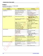
Page 53: ...d wire loose Clean and tighten ground LIGHTS FLICKERING Wires shorted or loose Locate insulate replace or tighten Grounding through fifth wheel Locate broken ground wire tractor or semitrailer LIGHTS...

Page 54: ...AD WEAR Over inflation Deflate to correct inflation See Tire Inflation on page 4 23 SHOULDER TREAD WEAR BOTH SHOULDERS Under inflation Increase inflation to correct PSI Check axle alignment See Tire I...

Page 55: ...gn axle See Axle Alignment on page 4 14 TRACKS TO EITHER SIDE Broken or bent springs or equalizers Replace defective parts Axles not parallel Re align axles AIR RIDE HEIGHT PROBLEMS TOO HIGH Axle to c...

Page 56: ...4 2 Worn brake shoe bushing Replace bushing Brake drum distortion Replace drum Broken brake chamber spring Replace spring Brake chamber pushrod binding Re align brake chamber bracket Air brake line l...

Page 57: ...BRAKES RELEASED Relay emergency valve leaking Repair or replace valve Leaking tubing or hose Replace defective part EXCESSIVE LEAKAGE WITH BRAKES APPLIED Relay emergency valve leaking Repair or replac...

Page 58: ...ting conditions or loads that create severe or excessive brake applications BRAKES PULL TO EITHER SIDE Drums of different diameters Replace with drums of same diameter Foreign matter in drums Clean dr...

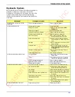
Page 59: ...tions for load limit See Standard Specifications on page 2 1 Slipping or broken pump drive Repair or replace couplings Check for alignment Valve Compensator stuck Clean Repair or Replace SYSTEM OPERAT...

Page 60: ...Low incorrect foamy oil Replace clean or add oil as needed Suction line plugged Clean out obstruction or replace line Flush system replace filter Pump damaged Repair or place LEAKY PUMP Damaged or wor...

Page 61: ...E a s t e r n W r e c k e r S a l e s I n c...

Page 62: ...chable Semitrailer Operator s Manual Re Order Part Number F 916 0217 LANDOLL CORPORATION 1900 North Street Marysville Kansas 66508 785 562 5381 800 428 5655 WWW LANDOLL COM F 916 0217 02 2017 Copyrigh...

Reviews: