ENGINE WITH FUEL SYSTEM
5-5
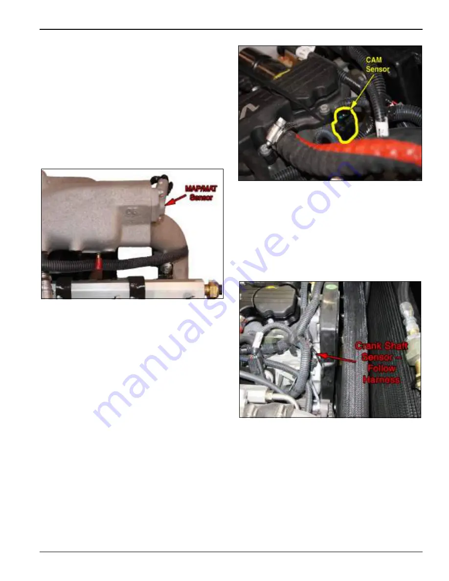
MAP Sensor and MAT Sensor
The MAP/MAT sensors are combined into one unit that is
fitted into a port in the intake manifold to allow it to read
MAT and MAP. The MAT portion of the sensor is a
negative coefficient thermistor. This means that as the
temperature goes up, the resistance drops. 5 volts is
supplied across the sensor The voltage drop, which
varies by temperature, is used to determine the manifold
air temp. The MAP sensor is a 5 volt pressure
transducer. When the pressure changes, the signal
voltage varies from .5 to 4.5 volts.
Figure 5-5: Map/Mat Sensor Location
CAM Sensor
The camshaft sensor is mounted towards the end of the
cylinder head. It is a Hall Effect sensor that is triggered by
a hole on the end of the cam shaft. The signal is one
pulse for every 2 engine revolutions, and is used to
phase the fuel injection with the proper engine stroke.
The engine will run without this signal but will have
throttle tip hesitation problems.
Figure 5-6: CAM Sensor Location
Crank Sensor
The crank position sensor is a reluctor sensor that is
triggered by a 60 -2 toothed wheel on the crankshaft. The
2 missing teeth are used to determine engines rotational
position. The crank sensor is the source of all other ECU
functions so if this sensor is not functioning the ECU will
not see an engine speed and will not provide fuel or
spark to the engine.
Figure 5-7: Crank Shaft Sensor Location
Fuel Rail, Fuel Pressure & LPG Injectors
The now gaseous LPG flows into the fuel rail where it is
distributed to the four LPG injectors. At the opposite end
of the fuel rail to the inlet port (5) there is a Fuel Absolute
Pressure (FAP) sensor, this sensor allows the ECU to
lengthen or shorten the fuel injector pulse width to
compensate for variations in the absolute fuel pressure
supplied to the injectors. The fuel injectors are held in
place in the fuel adapters (3) and the fuel injector
brackets (2). The fuel rail does not hold the injectors in
Summary of Contents for Bendi B40i4
Page 2: ......
Page 26: ...1 20 F 581 R1 INTRODUCTION SAFETY AND INSPECTION...
Page 100: ...3 52 F 581 R1 TROUBLESHOOTING AND CORRECTIVE MAINTENANCE...
Page 120: ...4 20 F 581 R1 CALIBRATION AND PROGRAMMING...
Page 129: ...ENGINE WITH FUEL SYSTEM 5 9 Figure 5 10 Fuel System Troubleshooting...
Page 133: ...ENGINE WITH FUEL SYSTEM 5 13...
Page 134: ...5 14 F 581 R1 ENGINE WITH FUEL SYSTEM...
Page 140: ...6 2 F 581 R1 GM ENGINE SUPPLIER PROVIDED DOCUMENTATION...


