background image

4-6

F-808-R0 

OPERATING THE B40I4 FORKLIFT

IMPORTANT

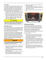
Make sure the release button on the buckle is set so 
you can unbuckle the seat belt quickly in an 
emergency.

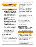
Figure 4-5: Seat Belt Latch

Seat Adjustments

A lever under the front of the seat releases the catch for 
forward or backward seat adjustment. See Figure 4-6. 
Weight or suspension adjustment is controlled by a seat 
adjustment. A gauge showing the adjusted level is 
located to the right of the adjustment handwheel.

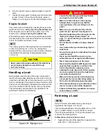
Figure 4-6: Seat Adjustments

Steering Wheel

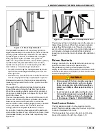
The steering wheel is equipped with a steering knob, 
which should be held firmly with your left hand at all 
times. See Figure 4-7.

Steering Column

CAUTION

The steering column is adjustable.

Release the tilt steering adjust clamp on the left side of 
the column and adjust the angle of the steering column. If 
loosened more you can also adjust the height of the 
steering column.

Tighten the clamp before driving the forklift.

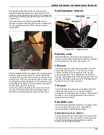
Figure 4-7: Steering Console Components

Adjusting the steering column while driving the 
truck is dangerous.

Adjustment of the column while driving will 
cause you to lose control of the truck.

Adjust the steering column only when the truck is 
not being driven.

Summary of Contents for Bendi B40i4

Page 1: ...F 580 R1 LANDOLL CORPORATION 1900 North Street Marysville Kansas 66508 785 562 5381 800 428 5655 WWW LANDOLL COM Model B40i4 Operator s Manual...

Page 2: ......

Page 3: ...0i4 Decals and Placement 1 3 Operator Safety 1 5 Lock Out Tag Out 1 6 Operator Safety Training 1 6 Seat Belt 1 6 Seat Safety Switch 1 6 Parking Brake 1 6 Tipping Hazards and Conditions 1 7 Longitudina...

Page 4: ...2 2 Fasteners 2 2 Horn Lights Etc 2 2 Hydraulic Lines and Loose Fittings 2 2 Hydraulic Oil Level 2 2 Dash Display 2 2 Stopping 2 2 Mast Operation 2 2 Overhead Guard 2 3 Parking Brake 2 3 Rust or Corr...

Page 5: ...rstanding Truck Rate Capacity 3 4 Truck Overview 3 4 Frame 3 5 Brake System 3 5 Parking Brake 3 5 Electrical System 3 5 Traction 3 5 LPG Gas Engine 3 5 Features 3 5 Keyswitch 3 5 Satety Interlock 3 6...

Page 6: ...ic Principles 3 11 Load Center 3 12 Counterweight 3 13 Maximum Fork Lift Height 3 13 Tilting Considerations 3 13 Attachments 3 13 Determining the Weight of the Load 3 13 Understanding Workplace Condit...

Page 7: ...h Display 4 7 Fork Positioner Non Side Shifting 4 7 Precautions for LP Gas Engines 4 7 Liquefied Petroleum Gas LPG 4 7 LPG Tank Removal 4 7 Refilling an LPG Tank 4 8 Installing an LPG Tank 4 8 Engine...

Page 8: ...ders Fittings Hoses 5 4 Hydraulic Oil 5 4 Operator Controls 5 4 Directional Control 5 5 Auxiliary Function Controls Optional 5 6 Horn 5 6 Lights and Alarm 5 6 Steering 5 6 Steer Column Tilt Telescope...

Page 9: ...rucks meet or exceed ASME B56 1 Part III Safety Powered Industrial Trucks IMPORTANT NO modifications or additions may be made to this forklift without prior written permission from Landoll Corporation...

Page 10: ...available for use Terminology and Illustrations Used in Manual Whenever front and rear right and left are mentioned throughout this manual it is assumed that you are seated in the vehicle looking tow...

Page 11: ...llustrated on the next page See Figure 1 1 on page 3 and a list of each machine decal is on the following page See Figure 1 2 on page 1 4 Make sure your check each machine sign before you operate your...

Page 12: ...1 4 F 808 R0 FORKLIFT SAFETY AND FAMILIARITY Figure 1 2 Decals...

Page 13: ...ng Maintain a safe distance from the edge of ramps platforms and other similar working surfaces When leaving the operator s compartment the forks must be lowered to the floor the mast must be placed i...

Page 14: ...naling that a driver is not in the operator s seat NOTE A two to three second delay is programmed into the seat switch to avoid nuisance shutdown and interruption of normal operations Parking Brake Th...

Page 15: ...aveling rapidly in either direction with or without a load An unloaded truck can tip easier than a loaded truck with the load lowered See Figure 1 5 the load is raised and the truck is being turned wh...

Page 16: ...rements are within the truck s capacity Truck stability and handling may be adversely affected Do not transport loads or other items within the operator s compartment or other areas of the truck Check...

Page 17: ...tc and must be replaced with the identical type It is recommended to use only Landoll authorized replacement parts WARNING 3 Whenever possible return the truck to a service area having sufficient ligh...

Page 18: ...1 10 F 808 R0 FORKLIFT SAFETY AND FAMILIARITY Table provided for general use NOTES...

Page 19: ...re involved service Preparing the Forklift 1 Check the hydraulic oil level See Hydraulic Oil on page 5 4 2 Check the engine oil level See Checking the Oil Level in the Service Manual Raise the engine...

Page 20: ...his to your supervisor and record it in the truck log book Have this operation checked and repaired before releasing the truck to use Fasteners Check for damaged loose or missing screws bolts and nuts...

Page 21: ...Welds Cracked or Broken Check for damage and reliability of welds Clean and repair immediately Do not use the truck Wires or Connectors Look for damaged cracked or broken insulation bare wires showin...

Page 22: ...ed exposure to sunlight will cause deterioration of rubber tires gaskets and hoses as well as vinyl seat coverings etc Towing the Truck If the truck breaks down and cannot be repaired at that location...

Page 23: ...st to its forward position straight ahead 2 Back the truck onto its carrier so that the forks are pointed away from the forward direction of motion 3 Set the mast to its forward level position and low...

Page 24: ...2 6 F 808 R0 RECEIVING AND INSPECTION Table provided for general use NOTES...

Page 25: ...lic control valve 12 volt DC battery Triplex or Quadplex high visibility mast configurations Lift capacity is a maximum of 4 000 lbs 1 814kgs at 24 600 mm load center Ergonomically designed operator c...

Page 26: ...ts on your Bendi B40i4 forklift 1 Forks 2 Load Backrest 3 Mast 4 Rear Drive Wheels 5 Steer Load Wheels 6 Overhead Guard 7 Steering Column wheel and knob 8 Drive and Stop Pedals 9 Dash Display 10 Engin...

Page 27: ...e Not Applicable Truck Type This designation assigned by the Underwriter s Laboratory UL Standard 558 describes the overall design of the components for the internal combustion engine powered truck Ty...

Page 28: ...d capacity how much weight it can safely lift and how to properly carry a load to maintain stability This weight is listed as the rated capacity on the identification plate See Figure 3 2 The rated ca...

Page 29: ...he parking brake system consists of an overcenter latch to hold the top pedal in the down position To continue the operator must first set the direction control lever to NEUTRAL release the parking br...

Page 30: ...the operator s input to the steering wheel Pressurized oil from the steering control valve is sent through a motion control valve to the hydraulic steering motor This motor turns actuator which rotate...

Page 31: ...mbination See Figure 3 2 The trucks are counterweighted to compensate for all positions up to the maximum allowed load Masts are engineered to distribute thrust loads evenly between the rollers and ra...

Page 32: ...dicate when the carriage and forks are perfectly level with the floor As an option trucks may be equipped with quad masts which utilize four sets of rails referred to as Outer Outer Intermediate Middl...

Page 33: ...3 11 Control Levers Direction Lever The forklift direction control lever is located on the operators control pod and selects the direction of travel of the truck forward or reverse See Figure 3 11 Lif...

Page 34: ...l The steering wheel is equipped with a steering knob which should be held firmly with your left hand at all times The steering column tilt and height are both adjustable using the tilt clamp See Figu...

Page 35: ...n imaginary point it will shift for various reasons The crucial thing to remember is as long as the center of gravity of the truck remains within the border of the stability triangle the truck will no...

Page 36: ...t is evenly distributed For example a load that is 48 in long has a horizontal load center of 24 in The further the load center is from the fulcrum the less stable the forklift Always make sure your l...

Page 37: ...may affect the load center When the factory dealer or distributor installs attachments approved by Landoll a modified identification plate is attached to the truck The new plate identifies the type of...

Page 38: ...ctrical panels Fire exits Emergency stop buttons Aisle ways Working in Hazardous Environments DANGER Chemical Hazards You should know the chemical characteristics of the substances you are moving In c...

Page 39: ...such as stability and rated capacity information you need to know before you operate your Landoll forklift Your employer is to make training available to ensure that you are competent to safely opera...

Page 40: ...Starting and Traveling Failure to follow this procedure will result in traction not being enabled 1 Make sure the LPG tank is properly mounted and connected Open tank valve slightly until pressure eq...

Page 41: ...round 4 Place in neutral turn the Keyswitch to the OFF position and remove the key NOTE Make sure all accessories are off lights etc before you turn the Keyswitch to the Off position Setting the Forks...

Page 42: ...to the truck ON and OFF and starts the engine Starter lockout prevents restart of running engine See Lock Out Tag Out on page 1 6 Drive Pedal The drive pedal is located on the floor to the right of th...

Page 43: ...ver away from the operator near the front of the armrest is the side shift lever See Figure 4 4 Side shift is a standard function on Bendi B40i4 forklifts Pull it back to shift to the right push it fo...

Page 44: ...nts Steering Wheel The steering wheel is equipped with a steering knob which should be held firmly with your left hand at all times See Figure 4 7 Steering Column CAUTION The steering column is adjust...

Page 45: ...remaining in the tank LPG Tank Removal Use the following procedure to remove the LPG tank 1 Removable LPG tanks can be replaced indoors only if the lift truck is a minimum of 25 feet 8 meters from an...

Page 46: ...f the fuel gauge Look at the fluid gauge and move the tank If the gauge needle does not move a new tank must be installed WARNING 2 Install the LPG tank in its bracket so that the alignment pin is in...

Page 47: ...11 item 5 The following illustrations show standard 40 in x 48 in W x L pallets loaded on a rack with 96 in beams The arrow labeled with an S shows the direction you must turn the steering wheel Follo...

Page 48: ...d 4 See Figures 4 11 and 4 12 5 Lift the forks to the required height and then level the forks using the tilt lever 6 Stop the forklift and turn the forks 90 using the steering wheel to align them wit...

Page 49: ...you still are unable to get enough clearance drive forward and try the removal process again To get more clearance don t start turning the forks until you have backed out 8 in to 16 in Figure 4 14 In...

Page 50: ...radient is 5 or less with a loaded Bendi B40i4 forklift and 8 or less if you are not carrying a load Always keep the load pointed uphill See Figure 4 18 Travel with the forks facing uphill whether you...

Page 51: ...edge of the aisle opposite the drop off point Item 2 See Figure 4 20 2 For wide aisles straighten out the truck so it is 36 in to 48 in from the side of the aisle where the load is located Item 6 See...

Page 52: ...until the load sits firmly on the rack Continue to lower the forks until they no longer support the load no load position See Figure 4 24 DANGER NOTE Do not tilt the mast back until the forks clear th...

Page 53: ...a small amount of discharge could cause it to slowly lose the rest of its pressure rendering the extinguisher useless In Case of a Fire WARNING The following directions are for general use only intend...

Page 54: ...4 16 F 808 R0 OPERATING THE B40I4 FORKLIFT Table provided for general use NOTES...

Page 55: ...explained in HEADING AND PAGE Recommended service inspections are based on normal operating conditions If the truck is subject to severe or above normal operating conditions extreme temperatures exces...

Page 56: ...Seat Switch Functioning properly Parking Brake Holds forklift in stopped position Drive Control Forward Reverse functioning smoothly Engine Air Cleaner Clean and check dust ejector Engine Belt Check...

Page 57: ...ing of the base band and tread separation Correct defects as soon as possible 4 Flat spotting can occur from excessive heat a load left on the forks overnight or locking the brakes with excessive skid...

Page 58: ...doors Operator Controls Lift Lower Control With the Keyswitch turned ON raise the mast The hydraulic motor should start running as soon as the control is moved out of the neutral position and stop as...

Page 59: ...ubricant and dirt buildup from within the channels 3 Using a small brush paint a thin film of grease to the sides top and bottom of the side shift channel surfaces reachable with the mast in this posi...

Page 60: ...Belt Slides Switch Check the seat covering for rips or cuts Check seat belt straps for cuts worn or frayed areas Make certain seat slides and adjustments lock in position Check that the seat belt is...

Page 61: ...Recommended Lubricants See Table 5 1 below for recommended lubricants For specific areas to lubricate the forklift See Figure 5 5 Table 5 1 Lubrication Chart Name Lubrication Comments 1 Chain SAE40W...

Page 62: ...5 8 F 808 R0 Figure 5 5 Lubrication Points...

Page 63: ...13 KPH Lift Speed Loaded Unloaded 90 fpm 27 mpm 70 fpm 21 mpm Lower Speed Loaded Unloaded 60 fpm 18 mpm 90 fpm 27 mpm Mast Tilt Forward Reverse 3 3 Standard Forks ITA Class II 40 x 4 x 1 5 in 1016 x 1...

Page 64: ...5 10 F 808 R0 Table provided for general use NOTES...
Page 65: ...Document Control Revision Log Date Revision Improvement s Description and Comments 03 01 11 F 580 R1 Initial Release Joshua 11 02 16 F 580 R1 Hydraulic fluid change Joshua...

Page 66: ...es Bendi Model B40i4 Narrow Isle Forklift Operator s Manual Re Order Part Number F 580 R1 LANDOLL CORPORATION 1900 North Street Marysville Kansas 66508 785 562 5381 800 428 5655 WWW LANDOLL COM F 580...

Reviews: