background image

973rev401

1J534

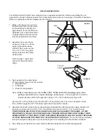
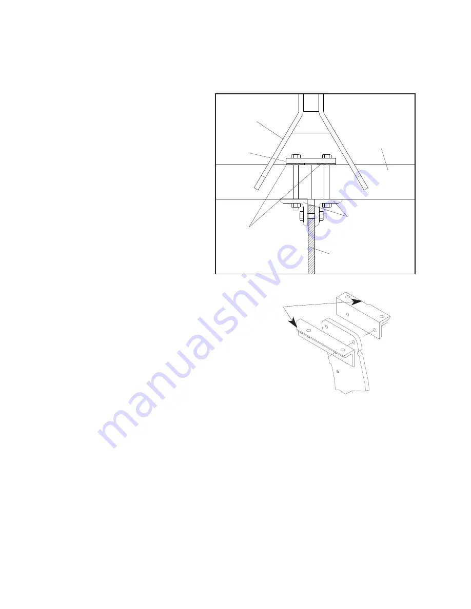
3. Next, assemble the outer shanks.

For each shank, mount to the frame tube:
1. plate weldment
2. 1J495 plate
3. shank mounting angles

Note: Make certain that you use the 

1J700, 1J701, 1J702, and 1J703


mounting angles at the

positions nearest the lower 3-point hitch lugs on the frame

.  These angles are trimmed to

 provide clearance at the hitch lugs when using a 19" or  20" shank spacing. Figure 2A.

Use the 3/4" x 8" long bolts in front and the 5/8" x 8" long bolts in the rear, but do not tighten at this
time.  (Refer to pages 6 and 7 of the repair part section for position of parts.)

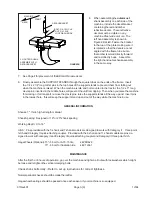
4. Assemble the shank between the mounting angles and install the bolts through the angles, shanks and

locknuts as shown, with two 5/8” x 3 3/4” long bolts at the front and a 3/4” x 3 1/2” bolt at the rear.

TIGHTEN THESE BOLTS UNTILTHE ANGLES ARE JUST SNUG AGAINST THE SHANK.    DO NOT
OVERTIGHTEN.  THE BOLTS SHOULD BE  EASILY TURNED WITH A WRENCH ON THE BOLT HEAD
WHEN CORRECTLY TIGHTENED.  OVER TIGHTENING THESE BOLTS WILL NOT ALLOW THE SHANK
TO PIVOT AND SHEAR THE FRONT BOLT IF AN OBSTRUCTION IS HIT.  

The front bolt that is installed

through the angles is designed only to keep the angles from spreading if the front shank bolt shears.

5. Now, adjust your shanks to the center distance desired and tighten the vertical clamping bolts.

2. Assemble the center shank,

as shown in Figure 1, with the
angles, plate and hardware
provided.  Be sure to use the
1/4 x 2 x 11 7/16" long shim
straps under the 1J497 plate
as illustrated.

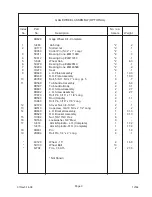
 Refer to page 7, repair parts
section, for proper hardware
usage.

SET-UP INSTRUCTIONS

Your Brillion Subsoil Chisel Plow is shipped to you in separate assemblies.  Before assembling the unit,
separate the various bundles and open the box assembly, taking care not to lose any of the parts or hardware.
(Refer to repair parts section for relative location of parts.)

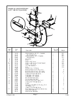
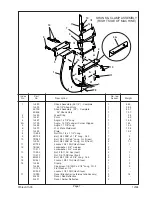
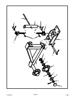
1. Block up the frame or mount it to

the three point hitch on the tractor
for the assembly of shanks and
gage wheels, if your machine is so
equipped.  See repair parts section
on gage wheels which shows how
they are assembled to the frame.

Shim Strap,
1/4” x 2” x 11 7/16”

Plate

Center
Shank

Angle

Mast

Frame

FIGURE 1

Trimmed
Angles

FIGURE 2A

Page 3-[a]

Summary of Contents for Brillion SCP-51

Page 1: ...899 1J534 973rev102 BRILLION FARM EQUIPMENT BRILLION WISCONSIN 54110 OPERATOR S MANUAL REPAIR PARTS CATALOG Models SCP 51 SCP 71 SCP 52 SCP 72 SCP 91 SCP 111 SCP 92 SCP 112 Subsoil Chisel Plo Subsoil...

Page 2: ...973rev401 1J534...

Page 3: ...ge I Introduction 3 Location Reference 3 Safety 3 Safety Suggestions 4 Operating Instructions 4 Specifications 6 Repair Parts 8 Coulter Assembly 8 9 Pulverizer Assembly 10 11 Parts Index 10 SUBSOIL CH...

Page 4: ...973rev401 1J534...

Page 5: ...chisel plow 5 Display the Slow Moving Vehicle emblem when traveling on roads 6 When traveling on the road at night make sure that reflective decals and accessory warning lights are mounted and visible...

Page 6: ...OT ALLOW THE SHANK TO PIVOT AND SHEAR THE FRONT BOLT IF AN OBSTRUCTION IS HIT The front bolt that is installed through the angles is designed only to keep the angles from spreading if the front shank...

Page 7: ...inserted in the middle holes will prevent the unit from tipping Then when you raise the machine for working or for transport remove the clevis pins raise the support stands all the way up and insert...

Page 8: ...L FOR CORRECT PROCEDURES 9 BLOCK IMPLEMENT TO PREVENT MOVEMENT WHEN UNHITCHED FROM TRACTOR 8J310 CAUTION 5 Page 4 17 16 15 CAUTION DEEPTILLOPERATIONCANDAMAGE UNDERGROUND UTILITIES CAUSING DANGEROUSCON...

Page 9: ...13 8 1J509 Shim 1 4 x 2 x 11 7 16 Lg not shown 2 1 5 8 1C210 Nut 3 4 10NC Hex 4 1 9 1C211 Lockwasher 3 4 Medium 4 10 1J523 Bolt 3 4 10NC x 8 Long Grade 5 4 1 1 11 6D758 Bolt 3 4 10NC x 3 1 2 Long Grad...

Page 10: ...1 5 10 7D040 Bolt 5 8 11NC x 8 Long Gr 5 rear 2 8 1J523 Bolt 3 4 10NC x 8 Long Gr 5 front 2 1 1 11 6C729 Locknut 3 4 10NC Hex Stover 1 1 12 1B166 Lockwasher 5 8 medium 2 1C211 Lockwasher 3 4 medium 2...

Page 11: ...7D040 Bolt 5 8 11NC x 8 Long Gr 5 rear 2 8 1J523 Bolt 3 4 10NC x 8 Long Gr 5 front 2 1 1 11 6C729 Locknut 3 4 10NC Hex Stover 1 1 12 1B166 Lockwasher 5 8 medium 2 1C211 Lockwasher 3 4 medium 2 13 1C39...

Page 12: ...973rev401 1J534 Page 8 FRONT 18 19 10 16 15 14 13 12 11 17 8 7 6 5 4 3 9 2 1...

Page 13: ...5 8 7 11 8D589 Turnbuckle Assembly 2 6 8 8D597 Turnbuckle Body 2 3 1 8D601 R H Screw Assembly 2 2 7 8D602 L H Screw Assembly 2 2 7 7C870 Roll Pin 3 16 x 1 1 8 Long 4 8D590 Rod Handle 2 1 1 7C940 Roll...

Page 14: ...973rev401 1J534 Page 10 5 8 4 6 7 9 2 3 1 18 17 16 15 14 13 12 11 10 4...

Page 15: ...9 2 8 4 5 8D602 L H Screw Assembly 2 2 7 6 8D597 Turnbuckle Body 2 3 1 7 8D601 R H Screw Assembly 2 2 7 8 8D590 Rod Handle 2 1 1 7C940 Roll Pin 3 16 x 7 8 4 9 7C870 Roll Pin 3 16 x 1 1 8 4 10 6D338 Se...

Page 16: ...shown 1 1 66 6 4K937 Machine Bolt 1 2 x 8 1 2 4 58 7 1C109 Lock Washer 1 2 8 01 8 1C390 Hex Nut 1 2 8 04 9 4K782 Machine Screw 1 2 x 1 1 4 8 01 10 6J150 Flange Lock Nut 1 4 8 11 3J662 Strap 2 1 5 12...

Page 17: ...nect end with green wire to right side lamp assembly Run wishbone harness wires along rear frame member to center of machine At center of machine assemble the connector of the straight harness to the...

Page 18: ...e toolbar and install the gauge wheel bracket Install the gauge wheel arm between the ears on the gauge wheel bracket and insert pivot shaft Secure with 1 2 x 2 roll pins Be sure that the hub points a...

Page 19: ...973rev401 1J534...

Page 20: ...973rev401 1J534...

Page 21: ......

Page 22: ...registration at all Landoll manufacturing facilities LANDOLL CORPORATION 1900 North Street Marysville Kansas 66508 785 562 5381 800 428 5655 WWW LANDOLL COM Copyright 2010 Landoll Corporation All righ...

Reviews: