2-12
1P342
ASSEMBLY INSTRUCTIONS
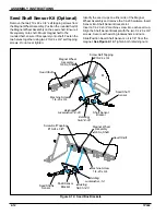
Seed Shaft Sensor Kit (Optional)
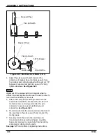
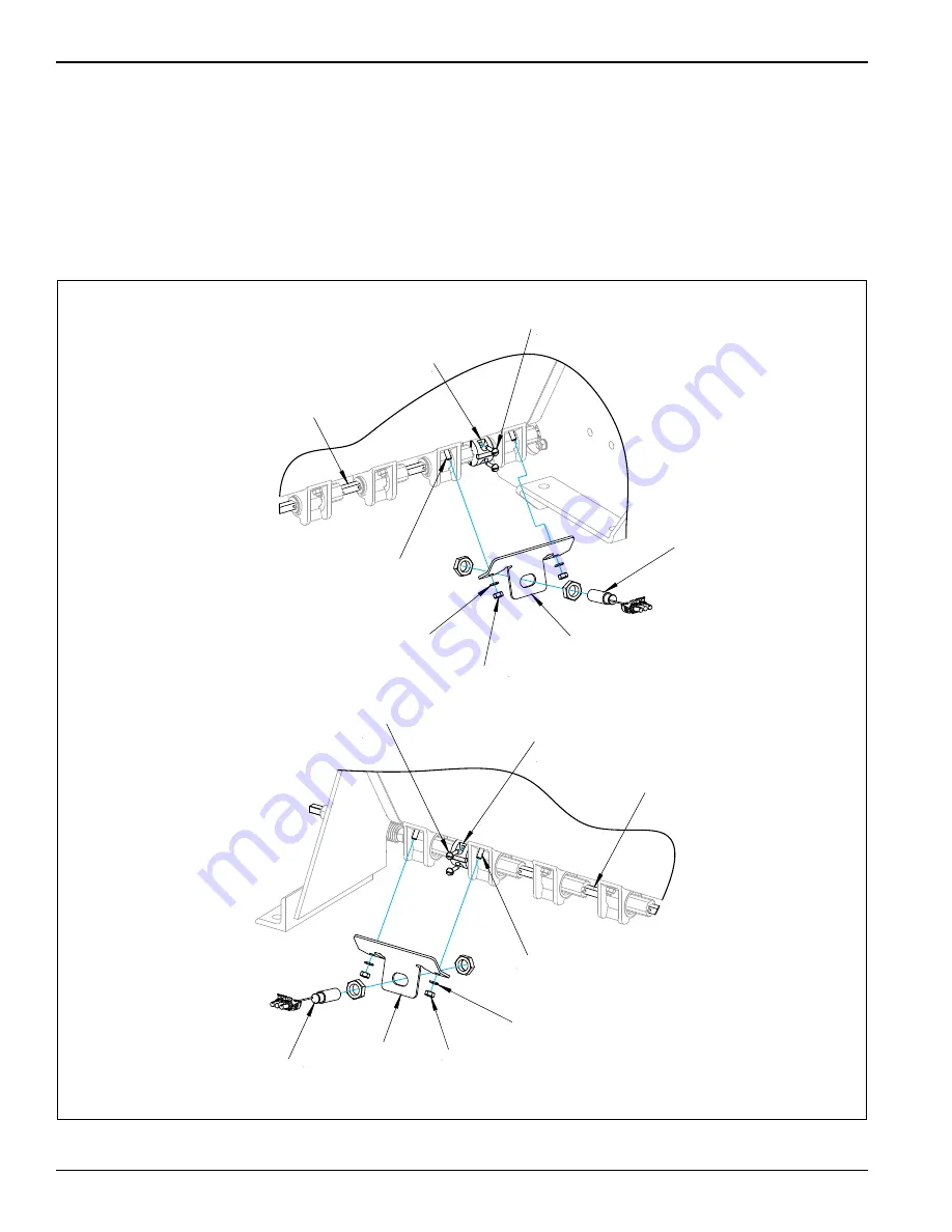
Remove the two #10 x 24 x 3/4” self tapping screws from
the Magnet Wheel Assembly. Position the rounded half of
the Magnet Wheel Assembly on the seed shaft. Ensure it
fits squarely onto shaft. Mount magnet half to the
rounded half. ensure it fits squarely onto shaft. Fasten the
two halves together using two #10-24 x 3/4” self tapping
screws.
Do not over tighten
.
Identify the seed cups on either side of the Magnet
Wheel Assembly and remove the 1/4-20 hardware. Insert
Sensor into Shaft Sensor Bracket slot.
Insert a 1/4-20 x 3/4” machine screw into each seed cup.
Align the Shaft Sensor Bracket with the two 1/4-20 x 3/4”
screws. Secure with existing lockwashers and nuts.
Slide/Position Seed Shaft Sensor so it is 1/8” from the
magnet.
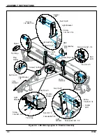
Figure 2-12: Seed Box Brackets
Seed Shaft
Magnet Wheel
Assembly
3/8 Sq Shaft
Screw,Self Tapping
#10-24 x 3/4
Existing
Nut,1/4-20
Shaft Sensor
Bracket
Seed Shaft
Sensor
Existing
Lockwasher,1/4
Machine Screw,
1/4-20 x 3/4
Screw,Self Tapping
#10-24 x 3/4
Seed Shaft
Magnet Wheel
Assembly
3/8 Sq Shaft
Machine Screw,
1/4-20 x 3/4
Existing
Lockwasher,1/4-20
Existing
Nut,1/4-20
Shaft Sensor
Bracket
Seed Shaft
Sensor
MidBoxSensorBrkts
Summary of Contents for BRILLION SL Series
Page 2: ......
Page 9: ...SAFETY INFORMATION 1 5 Decals Figure 1 3 8 Ft Model Decals 1 1 2 10 11 5 5 6 3 4 3 4 8 8 7 9...
Page 10: ...1 6 1P342 SAFETY INFORMATION Figure 1 4 10 Ft Model Decals 10 11 1 2 5 5 6 3 4 3 4 7 8 8 1 9...
Page 11: ...SAFETY INFORMATION 1 7 Figure 1 5 12 Ft Model Decals 11 2 1 10 3 4 5 5 6 3 4 9 8 1 7 8...
Page 12: ...1 8 1P342 SAFETY INFORMATION Figure 1 6 Hitch Decals 12 13...
Page 14: ...1 10 1P342 SAFETY INFORMATION Table provided for general use NOTES...
Page 21: ...ASSEMBLY INSTRUCTIONS 2 7 Table provided for general use NOTES...
Page 40: ...2 26 1P342 ASSEMBLY INSTRUCTIONS Table provided for general use NOTES...


