background image

OPERATION

3-5

Seed Rate Calibration

Machine may be calibrated for unlisted seed as follows:
1. Remove the drive bolt from the 6 tooth #A550 chain 

driven sprocket. 

See Figure 3-6.

2. Raise the machine and lock in the transport position.
3. Place a canvas or tarp to catch loose seed.

4. Turn the 15/16” hex on the transmission clockwise as 

follows:

•        136 revolutions for 8 foot seeder.
•        109 revolutions for 10 foot seeder.
•          91 revolutions for 12 foot seeder.
5. Weigh seed for the approximate planting rate in 

pounds per acre.

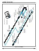
Figure 3-8:  Seed Rate Calibration

7227+

'5,9(5

7227+

237,21$/

7227+

'5,9(1

+(;

7227+

,'/(5

7,*+7(1(5

7227+

$'5,9(5

Summary of Contents for BRILLION SL Series

Page 1: ...807rev1215 1P342 LANDOLL CORPORATION 1900 North Street Marysville Kansas 66508 785 562 5381 800 428 5655 WWW LANDOLL COM Turfmaker Seeder Models SL and SLP 8 10 and 12 Operator s Manual...

Page 2: ......

Page 3: ...1 3 Protective Equipment 1 3 Chemical Safety 1 3 Prepare for Emergencies 1 3 Tire Safety 1 3 Decals 1 5 2 Assembly Instructions Pick Up Seeder Assembly 2 1 Pull Type Seeder Assembly 2 3 Drawbar Assemb...

Page 4: ...ttings for Loup Acre Meters Prior to 05 15 2012 3 8 4 Maintenance Adjustment General Torque Specifications 4 1 Hydraulic Fitting Torque Specifications 4 2 Fasteners 4 2 Tires 4 3 Lubrication 4 3 Chain...

Page 5: ...reference Right and Left designations in this manual are determined by facing the direction the machine will travel during field operation unless otherwise stated Owner Assistance If customer service...

Page 6: ...to clean the surface to remove any dirt or residue Where possible sign placement should protect the sign from abrasion damage or obstruction from mud dirt oil etc Keep Riders Off of Machinery DANGER...

Page 7: ...ed leaks Any fluid injected into the skin must be surgically removed within a few hours or gangrene may result Avoid the hazard by relieving pressure before disconnecting hydraulic lines NOTE On most...

Page 8: ...that the TOTAL weight of all towed implements A second chain should be used between each implement Attach the chain to the tractor drawbar support or specified anchor location Allow only enough slack...

Page 9: ...SAFETY INFORMATION 1 5 Decals Figure 1 3 8 Ft Model Decals 1 1 2 10 11 5 5 6 3 4 3 4 8 8 7 9...

Page 10: ...1 6 1P342 SAFETY INFORMATION Figure 1 4 10 Ft Model Decals 10 11 1 2 5 5 6 3 4 3 4 7 8 8 1 9...

Page 11: ...SAFETY INFORMATION 1 7 Figure 1 5 12 Ft Model Decals 11 2 1 10 3 4 5 5 6 3 4 9 8 1 7 8...

Page 12: ...1 8 1P342 SAFETY INFORMATION Figure 1 6 Hitch Decals 12 13...

Page 13: ...ot use fingers or skin to check for leaks Lower load or relieve hydraulic pressure before loosening fittings PARKING PIN 9J301 Turfmaker 4K401 13 TOOTH DRIVER 26 TOOTH OPTIONAL 37 TOOTH DRIVEN 15 16 H...

Page 14: ...1 10 1P342 SAFETY INFORMATION Table provided for general use NOTES...

Page 15: ...blocked securely so that it cannot roll NOTE Left and Right refer to directions seen as if standing behind the machine and facing in the direction of forward travel Pick Up Seeder Assembly When shippe...

Page 16: ...is located in a position similar to the parking pin 4 Install the LED Warning Lamps and Harnesses See Figures 2 7 2 8 and 2 10 CAUTION Figure 2 2 Shipping Bolt and Parking Pin Do not disengage pin unl...

Page 17: ...seeder in a work area that has a level surface and make sure it is blocked securely so that it cannot roll NOTE Left and Right refer to directions seen as if standing behind the machine and facing in...

Page 18: ...wbar Hydraulic Hoses 5 Install hub and spindles into the wheel arms and secure in outside hole farthest from the hub Secure with 1 2 13 x 3 Screws and Locknuts See Figure 2 5 6 Install wheels and tire...

Page 19: ...he machine See Figure 2 6 Figure 2 6 Shipping Bolt 8 Install the LED Warning Lamps and Harnesses See Figures 2 7 2 8 and 2 10 CAUTION Op WhlArm9J324HubTire Wheel Bolt 1 2 20 x 1 Locknut 1 2 13 Spindle...

Page 20: ...ceptacle free of dirt and corrosion 2 Make sure the 7 pin connector is inserted ALL the way in With tighter fitting pins operator may think the connector is all the way in but really isn t 3 Make sure...

Page 21: ...ASSEMBLY INSTRUCTIONS 2 7 Table provided for general use NOTES...
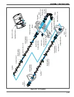
Page 22: ...bly W0LG R OHFW UDZEDU 609 LJKW DU 5HG 6FUHZ 1XW ODW DVKHU 6FUHZ PEHU 6FUHZ 1XW LJKW UDFNHW 6FUHZ RFNZDVKHU 1XW LJKW UDFNHW 6FUHZ RFNZDVKHU 1XW PEHU 6FUHZ 1XW 1XW LJKW 0RGXOH 7LH 6WUDS 6FUHZ 3LQ DUQHV...

Page 23: ...d along the front of frame up the outer Light Bracket and plug it into the Amber LED 7 Repeat for the Left Side Yellow Tape 8 Plug the 7 Pin Harness into the Light Module then route the harness along...

Page 24: ...Lights 8 3 Pt Assembly W 2S0LG R OHFW 3W 0RXQW 7LH 6WUDS 3LQ DUQHVV 609 609 0RXQW 1XW ODW DVKHU 6FUHZ PEHU 6FUHZ 1XW LJKW UDFNHW 6FUHZ 1XW DVKHU PEHU 6FUHZ 6FUHZ LJKW UDFNHW DVKHU 1XW 1XW LJKW 0RGXOH...

Page 25: ...s with Green Tape along the front right side of the frame up the outer Light Bracket and plug the 2 prong cord into the Amber LED Plug the 3 prong cord into the Red LED 8 Repeat for the Left Side Yell...

Page 26: ...sor into Shaft Sensor Bracket slot Insert a 1 4 20 x 3 4 machine screw into each seed cup Align the Shaft Sensor Bracket with the two 1 4 20 x 3 4 screws Secure with existing lockwashers and nuts Slid...

Page 27: ...ASSEMBLY INSTRUCTIONS 2 13 Figure 2 13 Seed Shaft Sensor Mounting Dimension Seedmeter 1 8 Max Magnet Wheel Assembly Shaft Sensor Bracket Seed Shaft Sensor Magnet SeedShaftSensorDim...

Page 28: ...onment See Figure 2 14 6 Connect plug labeled Left Front Seed Shaft Sensor to the left front Seed Shaft Sensor Seal the plug end using a 3 Pin Tower and Cavity Plugs to protect it from the environment...

Page 29: ...1 2 bolt and locknut 5 Install one of the center shafts in the agitator from Step 4 6 Install the second agitator Secure with 1 4 20 x 1 1 2 bolt and locknut 7 Install center bearing and shaft Secure...

Page 30: ...ole 9 1 2 Lockwasher 5 16 Lockwasher 5 16 Nut 3 8 16 Lockwasher 3 8 Flat Washer 3 8 Chain Tension Bar Flat Washer 3 8 Bolt 3 8 16 x 1 1 4 Shaft Agitator 2 Hole 5 1 4 Shaft Agitator 3 Hole 5 1 4 Shaft...

Page 31: ...1 4 Shaft Agitator 1 Hole 3 7 8 Shaft Agitator 2 Hole 5 1 4 Bolt 1 4 20 x 1 1 2 Bearing and Collar Flangette 19 Tooth Sprocket Slotted Pin Chain Bolt 5 16 18 x 1 1 2 Seedbox Divider Rivet 187 x 3 16...

Page 32: ...7 8 Shaft Agitator 2 Hole 5 1 4 Bolt 1 4 20 x 1 1 2 Flangette 19 Tooth Sprocket Slotted Pin Chain Seedbox Divider Rivet 187 x 3 16 Shaft Agitator 2 Hole 4 1 2 Lockwasher 5 16 Bolt 5 16 18 x 1 1 2 Fla...

Page 33: ...d nuts See Figure 2 20 2 Attach the pick up switch to the top of the 5K714 bracket with two 8 32 x 1 1 4 machine screws flat washers lock washers and nuts Do not tighten screws at this time See Figure...

Page 34: ...5 Attach the short pickup switch ground wire to the small hole in the 5K714 bracket with a 6 32 x 1 2 machine screw removing paint under the wire connector to assure a good electrical ground connectio...

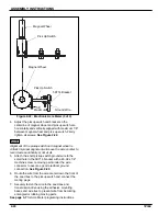
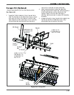
Page 35: ...ts loosely and assemble scraper angle to them Attach two center scrapers at center hole locations and then attach all of the regular scrapers Center entire assembly on machine position scrapers for pr...

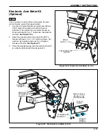
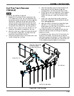
Page 36: ...tine and 2 1 2 points on each side If needed additional tines may be purchased and installed This kit must be used with standard 9J442 long three point hitch on pickup machines The Wheel Track Remove...

Page 37: ...g angle from swinging with a 1 2 clevis pin and hair pin cotter 6 Fasten the bar and tine assemblies to the adjusting angles with 1 2 x 1 3 4 capscrews and locknuts Tighten the locknuts to allow the f...

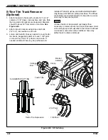
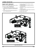
Page 38: ...ket hubs on the front transmission shaft 4 Remove locking collar from left side of the front transmission shaft 5 Remove bearing bolts from right side of the front transmission shaft 6 Move shaft far...

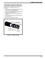
Page 39: ...4C689 Sand Wheel See Figure 2 27 2 At the end of the process slide a Half Wheel onto the axle next to the last Wheel Spacer 3 Slide the Clamp Band over the axle and next to the Half Wheel 4 Insert 1...

Page 40: ...2 26 1P342 ASSEMBLY INSTRUCTIONS Table provided for general use NOTES...
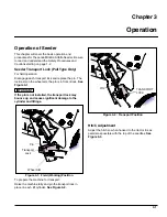
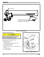
Page 41: ...heel arm the pin is in front of lock See Figure 3 1 IMPORTANT If the pin is not installed the transport lock may bounce up and cause significant damage to the cylinder and fittings Figure 3 1 Field Wo...

Page 42: ...Pin When unhooking the seeder 1 Remove the Klik Pin push in Parking Pin replace the Klik Pin 2 Disconnect the tractor For clarity See Figure 3 4 Figure 3 4 Parking and Klik Pins parallel as possible...

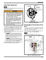
Page 43: ...7 Seed cups discharge to the front of the machine to aid the operator in determining proper operation Figure 3 5 Micro Meter Disengaging Transmission Drive Bolt A 1 4 20 x 2 1 4 grade 5 bolt connects...

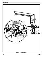
Page 44: ...42 OPERATION Figure 3 7 Seed Rate Adjustment Increase Shaft Moves This Direction Decrease Shaft Moves This Direction Seed Rate Adjusting Nut Large Locknut Important Do Not Loosen Or Adjust These Nuts...

Page 45: ...ock in the transport position 3 Place a canvas or tarp to catch loose seed 4 Turn the 15 16 hex on the transmission clockwise as follows 136 revolutions for 8 foot seeder 109 revolutions for 10 foot s...

Page 46: ...e Chart 1 RATES ARE FOR 13 TOOTH DRIVER DOUBLE THESE VALUES FOR 26 TOOTH DRIVER 2 RATES ARE INTENDED AS A GUIDE ONLY VARIATIONS IN SIZE AND CLEANLINESS WILL AFFECT RATES CHECK ACREAGE AND POUNDS OF SE...

Page 47: ...button the Acre Counter will accept the number in the display as the new pulses per 400 feet See Table 3 1 2 If you do not know the pulses per 400 feet press and hold the UP and DOWN buttons until th...

Page 48: ...for the model listed in the chart See Table 3 Press the function button to set the pulses If screen goes blank before you press the function button repeat steps 1 and 2 4 Press the function button to...

Page 49: ...SS308 29 8 0 SSP310 SS310 29 10 0 SSP312 SS312 29 12 0 SLP8 SL8 314 8 0 SLP10 SL10 314 10 0 SLP12 SL12 314 12 0 SLP204 SLP2041 128 4 0 SLP206 SLP2061 128 6 0 SLP304 SLP3041 64 4 0 SLP306 SLP3061 64 6...

Page 50: ...2 SSP308 SS308 382 8 SSP310 SS310 382 10 SSP312 SS312 382 12 SLP8 SL8 4147 8 SLP10 SL10 4147 10 SLP12 SL12 4147 12 SLP204 SLP2041 1690 4 SLP206 SLP2061 1690 6 SLP304 SLP3041 845 4 SLP306 SLP3061 845 6...

Page 51: ...0 40 50 65 81 90 112 9 16 12 55 62 80 100 110 137 9 16 18 60 75 90 112 130 162 5 8 11 75 94 110 137 170 212 5 8 18 85 106 130 162 180 225 3 4 10 130 162 200 250 280 350 3 4 16 150 188 220 275 320 400...

Page 52: ...ressure lubricants are used When fasteners are dry solvent cleaned add 33 to as received condition torque Bolt head identification marks indicate grade and may vary from manufacturer to manufacturer T...

Page 53: ...stantly raised When the machine is not used for some time exposed portions of the hydraulic cylinder rods must be cleaned and covered with a thick coat of grease to prevent corrosion which will damage...

Page 54: ...All cups should be closed If not there are three adjustments to make as needed See Figure 4 5 1 Jam nuts on both ends of the micrometer are used to adjust all cups the same amount 2 Loosen the feed ro...

Page 55: ...JAM NUT SEED RATE ADJUSTING NUT LARGE LOCKNUT 3 Individual cups can be adjusted by loosening their mounting bolts moving cups and then re tightening 2 Loosen feed roll coupling jam nuts and set screws...

Page 56: ...first Loosen clamp bands and slide wheels snug against each other centering the entire assembly under the deflector shields Locate the bolt in the clamp band over the weld on the pipe Slide the clamp...

Page 57: ...OR ADAPTER 08MJ x 08MOR HOSE ASM 134 TEE 08MJx 08MJ x 90 HOSE ASM 105 12 Machines HOSE ASM 94 10 Machines HOSE ASM 85 8 Machines CYLINDER 2 1 2 x 6 CYLINDER 2 1 2 x 6 ELBOW 08FJS x 08MJ x45 ELBOW 08FJ...

Page 58: ...p Switch face with it re connected to the display and see if the display increments up If not put an ohm meter or continuity tester on the contacts of the Pick up Switch harness and place a magnet in...

Page 59: ...up type smooth wheels Weights and Dimensions Approximate SL8 2029 SL10 2394 SL12 2842 SSL8 1989 SSL10 2112 SSL12 2544 SLP8 1720 SLP10 2074 SLP12 2460 SSLP8 1680 SSLP10 1792 SSLP12 2162 Physical Charac...

Page 60: ...95 Speed Up Kit doubles output of all seed boxes 3 3 3 9J932 Coil Tine Tire Track Remover Kit for use with all hitches 105 105 105 1K225 8ft Scraper Kit for front wheels 85 1K224 10ft 115 2K526 12ft 1...

Page 61: ...Control Revision Log Date Revision Improvement s Description and Comments 07 2008 Initial Release 09 2013 807rev0913 Added LED Warning Lights Updated Drawings 12 15 807rev1215 Decal Locations Updated...

Page 62: ...er Seeder Models SL and SLP 8 10 and 12 Operator s Manual Re Order Part Number 1P342rev1215 LANDOLL CORPORATION 1900 North Street Marysville Kansas 66508 785 562 5381 800 428 5655 WWW LANDOLL COM 807r...

Reviews: