background image

1-2

7K555

SAFETY INFORMATION

Federal law requires that you explain the safety and 
operating instructions furnished with this implement to all 
operators before they are allowed to operate the 
implement. These instructions must be repeated to the 
operators at the beginning of each season. Be sure to 
observe and follow the instructions for the safety of 
anyone operating or near the implement.

NOTE

Investigation has shown that nearly 1/3 of all farm 
accidents are caused by careless use of machinery. 
Insist that all people working with you or for you abide by 
all safety instructions.

Understanding Safety 

Statements

You will find various types of safety information on the 
following pages and on the implement decals (signs) 
attached to the vehicle. This section explains their 
meaning.

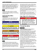
NOTICE

CAUTION

WARNING

DANGER

NOTE

You should read and understand the information 
contained in this manual and on the implement decals 
before you attempt to operate or maintain this equipment.

Examine safety decals and be sure you have the correct 
safety decals for the implement. See Safety Sign and 
Locations for decal locations. See Figures 1-2, 1-3 and 
1-4.

Order replacement decals through your Brillion dealer.
Keep these signs clean so they can be observed readily. 
It is important to keep these decals cleaned more 
frequently than the implement. Wash with soap and water 
or a cleaning solution as required.
Replace decals that become damaged or lost. Also, be 
sure that any new implement components installed 
during repair include decals which are assigned to them 
by the manufacturer.
When applying decals to the implement, be sure to clean 
the surface to remove any dirt or residue. Where 
possible, sign placement should protect the sign from 
abrasion, damage, or obstruction from mud, dirt, oil etc.

Keep Riders Off of Machinery

DANGER

Transporting Safety

IMPORTANT

It is the responsibility of the owner/operator to 
comply with all state and local laws.

When transporting the implement on a road or highway, 
use adequate warning symbols, reflectors, lights and 
slow moving vehicle sign (purchased separately), as 
required. Slow moving tractors and towed implements 
can create a hazard when driven on public roads. They 
are difficult to see, especially at night.
Do not tow an implement that, when fully loaded, weighs 
more than 1.5 times the weight of the towing vehicle.
Carry reflectors or flags to mark tractor and implement in 
case of breakdown on the road.
Do not transport at speeds over 20 MPH under good 
conditions. Never travel at a speed which does not allow 
adequate control of steering and braking. Reduce speed 
if towed load is not equipped with brakes.
Avoid sudden stops or turns because the weight of the 
implement may cause the operator to lose control of the 
tractor. Use a tractor 1.5 times heavier than the 
implement.
Use caution when towing behind articulated steering 
tractors; fast or sharp turns may cause the implement to 
shift sideways.

Special notice - read and thoroughly understand.

Proceed with caution. Failure to heed caution 
may cause injury to person or damage product.

Proceed with caution. Failure to heed warning will 
cause injury to person or damage product.

Proceed with extreme caution. Failure to heed 
notice will cause injury or death to person and/or 
damage product.

  • Do not allow extra riders on tractor or a             

machine. Riders could be struck by foreign 
objects or thrown from the implement.

  • Never allow children to operate equipment.
  • Keep bystanders away from the implement 

during operation.

Summary of Contents for Brillion SSP4

Page 1: ...7K55rev0620 06 2020 to Present LANDOLL COMPANY LLC 1900 North Street Marysville Kansas 66508 785 562 5381 800 428 5655 WWW LANDOLL COM s Sure Stand Seeder Models SSP4 SSP5 and SSP6 Operator s Manual...

Page 2: ......

Page 3: ...3 Maintenance Safety 1 3 High Pressure Fluid Safety 1 3 Protective Equipment 1 3 Chemical Safety 1 3 Prepare for Emergencies 1 3 2 Assembly of Optional Equipment Agitator Blades Optional Cage or Brush...

Page 4: ...ssword 3 10 Quick start Settings for Loup Acre Meters Prior to 05 15 2012 3 10 To Program Meter 3 10 To Enter Password 3 10 To Disable Password 3 10 Battery Replacement 3 10 4 Maintenance Specificatio...

Page 5: ...contact your Brillion dealer Your implement s parts should only be replaced with Brillion parts Have the Serial Number and complete Model Number available when ordering parts from your Brillion deale...

Page 6: ...ove any dirt or residue Where possible sign placement should protect the sign from abrasion damage or obstruction from mud dirt oil etc Keep Riders Off of Machinery DANGER Transporting Safety IMPORTAN...

Page 7: ...under pressure can be nearly invisible and have enough force to penetrate the skin causing serious injury Use a piece of cardboard rather than hands to search for suspected leaks Any fluid injected in...

Page 8: ...Red Clover Alyce Calif Bur Crimson Hubam Crested Wheat Crown Vetch Flax Harding Grass Klein Grass Lespedeza KoreanUnhulled Lespedeza Korean Hulled Lespedeza Sericea Unhulled Lespedeza Sericea Hulled L...

Page 9: ...SAFETY INFORMATION 1 5 Figure 1 3 SSP4 Decals 3ODWH...

Page 10: ...1 6 7K555 SAFETY INFORMATION Figure 1 4 SSP5 and 6 Decals 3ODWH...

Page 11: ...T Before proceeding with any agitator installation be sure to determine the direction of shaft rotation on your particular seeder model See Figure 2 1 Figure 2 1 Shaft Rotation Changing Agitator Kits...

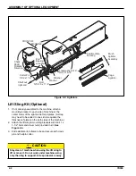
Page 12: ...machine 2 Attach the lift sling to mounting brackets with 5 8 11 x 1 1 2 bolts and stover nuts provided in kit See Figure 2 3 3 Slide stabilizer into frame tube and secure with clevis pin and hairpin...

Page 13: ...ASSEMBLY OF OPTIONAL EQUIPMENT 2 3 Figure 2 3 Lift Sling Kit 67 1 5 5 0RXQWLQJ UDFNHW 0RXQWLQJ UDFNHW DLUSLQ RWWHU OHYLV 3LQ ROW 6WDELO HU 1XW ROW 1XW LIW 6OLQJ 67 1 5 5 67 1 5 5...

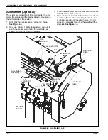
Page 14: ...t which holds the acre meter as shown onto the left front of the seedbox 3 Mount the acre meter onto this bracket with 10 24 x 1 bolts lockwashers and nuts 4 Then run the wire from the bottom of the m...

Page 15: ...its longer wire up toward the side of the seedbox to meet the wire from the acre meter Attach its shorter wire to the ground on the bracket Remove paint under the terminal to assure a good electrical...

Page 16: ...2 6 7K555 ASSEMBLY OF OPTIONAL EQUIPMENT Page Intentionally Blank...

Page 17: ...2 Remove the Klik pin pull the parking pin into outer position replace the Klik pin See Figure 3 1 When unhooking the seeders 1 Remove the Klik pin push in the parking pin replace the Klik pin See Fi...

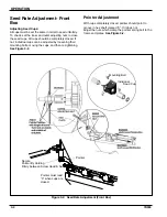
Page 18: ...by loosening their mounting bolts moving the cups and then re tightening See Figure 3 2 Pointer Adjustment With cups completely closed pointer should point to groove in hex shaft marked 0 If it does n...

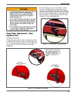
Page 19: ...x should then be completely covered See Figure 3 4 Figure 3 3 Agitator Box Control Handle Figure 3 4 Adjusting the Box Slide To prevent damage to the seed meters do not apply excessive force to adjust...

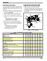
Page 20: ...ver Sprocket Rates are intended as a guide only Variations in size and cleanliness will affect rates Check acreage and pounds of seed used for best results See Table 3 1 and Table 3 2 Figure 3 5 Chain...

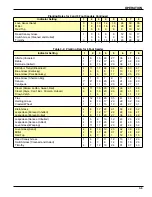
Page 21: ...Blue Grass Sherman Big Canola Centipede 1 4 1 8 8 5 13 11 7 20 15 8 25 20 11 31 24 12 36 27 13 43 31 Clover Alsike Ladino Sweet Red Clover Alyce Calif Bur Crimson Hubam Crown Vetch 4 4 11 8 1 15 13 4...

Page 22: ...ATES FOR BROME BOX REAR BOX IN POUNDS PER ACRE Rates are for 13 Tooth Driver Sprocket Rates are intended as a guide only Variations in size and cleanliness will affect rates Check acreage pounds of se...

Page 23: ...lt and adjust to obtain about 1 8 1 4 of deflection Re tighten axle bolt Be careful not to over tighten To adjust the 3rd drive chain loosen the 3 4 Hex bolt and adjust to obtain just enough sag so th...

Page 24: ...ll cause the clamp band to loosen and slide Adjust the front roller wheels first Loosen clamp bands and slide the wheels snug against each other centering the entire assembly under the deflector shiel...

Page 25: ...o not know the pulses per mile press and hold the UP and DOWN buttons until the 0000 appears in the display The PULSES LED will blink The acre counter is now counting shaft rotations Enter the cab and...

Page 26: ...function button to set the width If screen goes blank before you press the function button repeat steps 4 and 5 7 Press the function to scroll through the screens to check that the correct pulses and...

Page 27: ...SS308 29 8 0 SSP310 SS310 29 10 0 SSP312 SS312 29 12 0 SLP8 SL8 314 8 0 SLP10 SL10 314 10 0 SLP12 SL12 314 12 0 SLP204 SLP2041 128 4 0 SLP206 SLP2061 128 6 0 SLP304 SLP3041 64 4 0 SLP306 SLP3061 64 6...

Page 28: ...2 SSP308 SS308 382 8 SSP310 SS310 382 10 SSP312 SS312 382 12 SLP8 SL8 4147 8 SLP10 SL10 4147 10 SLP12 SL12 4147 12 SLP204 SLP2041 1690 4 SLP206 SLP2061 1690 6 SLP304 SLP3041 845 4 SLP306 SLP3061 845 6...

Page 29: ...40 50 65 81 90 112 9 16 12 55 62 80 100 110 137 9 16 18 60 75 90 112 130 162 5 8 11 75 94 110 137 170 212 5 8 18 85 106 130 162 180 225 3 4 10 130 162 200 250 280 350 3 4 16 150 188 220 275 320 400 7...

Page 30: ...from manufacturer to manufacturer Thick nuts must be used on grade 8 capscrews Use value in if using prevailing torque nuts Dash Size 37 Deg JIC O ring ORS O ring boss 4 11 13 15 17 13 15 5 14 16 21 2...

Page 31: ...use check the entire machine and tighten any loose nuts or bolts Daily or periodic checks should be made thereafter Values are given in foot pounds Use GRADE B lock nuts with GRADE 2 and GRADE 5 bolts...

Page 32: ...inches 84 inches Overall Length w out Lift Sling 30 inches 30 inches 30 inches Overall Height w out Lift Sling 43 inches 43 inches 43 inches Seed Box Capacity 3 1 2 bushels 4 3 8 bushels 5 1 4 bushel...

Page 33: ......

Page 34: ...Stand Seeder Models SSP4 SSP5 and SSP6 Operator s Manual Re Order Part Number 7K555rev0620 LANDOLL COMPANY LLC 1900 North Street Marysville Kansas 66508 785 562 5381 800 428 5655 WWW LANDOLL COM 7K55...

Reviews: