


2-18
1P124-2306
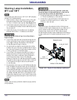
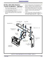
Brillion Elite Mini Monitor -
Optional
IMPORTANT
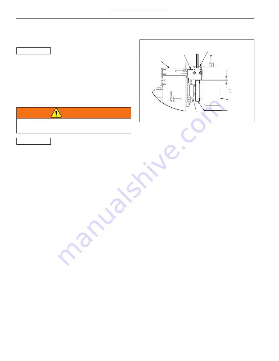
The Brillion Elite Mini Monitor System by Loup
utilizes a MUX communication line. Sensors must be
learned into the Monitor. Location of each pre-learned
Smart Shaft Sensor or Bin Level Sensor is important
for proper Monitor display. Each Sensor utilizes 3
wires (+, -, MuxBus) to connect to the system. The
Sensors do not require specific Harness connection
points. Each Sensor is identified in the Monitor by its
own signal.
WARNING
IMPORTANT
All Harnesses must be firmly attached to Machine
Frame members so they do not sag or become torn
loose by field debris.
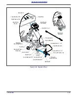
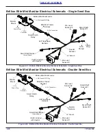
Refer to Brillion Elite Mini Monitor Single or Double Box
Electrical Schematic.
and
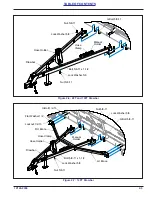
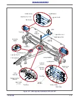
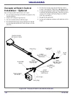
1. Lay out the Seeder Harness on the front of the Seeder
ensuring that the Electric Clutch 2-Pin Connector is
on the left side. The Seeder Harness 24" Branch
connects to the LH Bin Level Sensor.
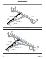
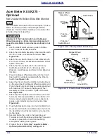
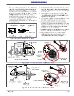
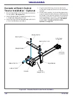
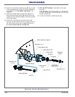
2. Remove Seeder Clutch. Install Actuator Assembly
onto the Quill Shaft outer diameter, securing with
Actuator Assembly Set Screw. Reinstall Clutch.
Install Pick-up Switch Bracket to the
Transmission Input Shaft Bearing Flangette Hardware.
Assemble Smart Shaft Sensor onto the Pick-Up Switch
Bracket with sensor provided hardware and #8-32
Flange Locknuts. Adjust the Smart Shaft Sensor so
that it is 1/8" Max away from the Actuator Assembly.
Connect Ground Speed Smart Shaft
Sensor to the Center Seeder Harness.
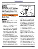
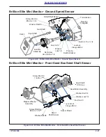
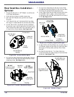
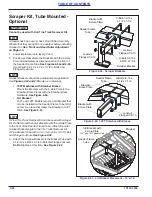
3. Front RH side Seed Box between the 2nd and 3rd
Seed Meters, install Magnet Wheel Assembly on the
Hex Seed Shaft.
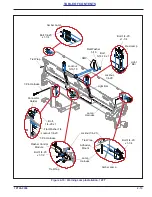
Remove the 3rd
and 4th Seed Meter front Round Head Machine
Screws that mount the Seed Meter to the Seed Box
and replace them with 1/4-20 x 1 Round Head
Machine Screws. Install the Sensor Mount on the
1/4-20 x 1 Machine Screws. Secure with Flat
Washers, Lock Washers and Nuts. Install a Smart
Shaft Sensor to the Sensor Mount with sensor
provided hardware and #8-32 Flange Locknuts.
Adjust the Smart Shaft Sensor so that it is 1/8" Max
away from the Magnet Wheel Assembly on the Seed
Shaft.
Connect the Smart Seed
Shaft Sensor to the Seeder Harness.
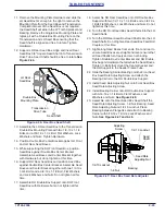
Figure 2-27: Ground Speed Sensor Detail
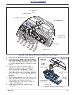
4. If equipped with a Rear Seed Box, removed the RH
Rear Deflector and replace it with notched RH Rear
Deflector which allows access to the Smart Shaft
Sensor.
between the 2nd and 3rd Seed Meters, place 1-1/4 x
1/4 x 1/16 Magnet on the Seed Shaft. Secure with
Magnet Collar. Remove the 1st and 2nd Seed Meter
rear Round Head Machine Screws that mount the
Seed Meter to the Seed Box and replace them with
1/4-20 x 3/4 Round Head Machine Screws. Install the
Sensor Mount on the 1/4-20 x 3/4 Machine Screws.
Secure with Flat Washers, Lock Washers and Nuts.
Install a Smart Shaft Sensor to the Sensor Mount with
sensor provided hardware and #8-32 Flange
Locknuts. Adjust the Smart Shaft Sensor so that it is
1/8" Max away from the Magnet Collar on the Seed
Shaft.
Shaft Sensor to the Seeder Harness.
5. In not equipped with a Rear Seed Box, seal the
Seeder Harness Connector with a 3-Pin Shroud and
Cavity Plugs to protect the Harness from the
environment.
6. The Seeder RH and LH ends only, remove the .803
Knockouts in the Seed Box.
Do Not remove the
Knockouts in the Seed Boxes at the center of the
Seeder.
7. On the inside at either end of the Seed Box, install a
Bin Level Sensor Bracket with the Seed Box Mounting
3/8-16 Hardware.
Determine the
desired level for the alarm to be indicated on the
Brillion Elite Mini Monitor and assemble the Bin Level
Sensors to Bin Level Sensor Brackets with sensor
provided hardware and #8-32 Flange Locknuts. If more
adjustment is needed, the Bin Level Sensor Brackets
can also be raised or lowered to the desired seed level.
Install Cord Grips from the inside of the Seed Box out
High Power Magnet is use. See “High Power
Magnet” on Page 1-2.
1/8"
Max
Pick-Up Switch
Bracket
Smart Shaft
Sensor
Actuator
Assembly
Clutch
Transmission
Bearing
Summary of Contents for Brillion Turfmaker III Series
Page 4: ......
Page 14: ...1 6 1P124 2306 TABLE OF CONTENTS Figure 1 4 Decal Placement Hitch SL2 HitchDecals 1 9 1 9 3...
Page 18: ...1 10 1P124 2306 TABLE OF CONTENTS Table provided for general use NOTES...
Page 45: ...1P124 2306 2 27 TABLE OF CONTENTS Table provided for general use NOTES...
Page 49: ...1P124 2306 2 31 TABLE OF CONTENTS Table provided for general use NOTES...
Page 57: ...1P124 2306 2 39 TABLE OF CONTENTS Table provided for general use NOTES...
Page 74: ...3 14 1P124 2306 TABLE OF CONTENTS Table provided for general use NOTES...
Page 102: ...6 4 1P124 2306 TABLE OF CONTENTS Table provided for general use NOTES...


