background image

3-2

F-459-R1

HYDRAULIC OIL, MOTORS, PUMPS AND CYLINDERS

1.

Lower the mast to the floor, then tilt it back
completely.

2. Turn the key switch to OFF, remove the hydraulic tank

access cover.

3.

Remove the dipstick, holding the dipstick tip level,
check the oil level. If the oil level is at
the FULL line or between the FULL
and ADD lines, the level is correct and
no oil is needed. If the oil is at or below
the ADD line, you will need to add oil to
bring it up to the FULL line (maximum).

4.

Add hydraulic oil as needed. See
page 1-7 for hydraulic oil
specifications.

5.

If the fluid appears very dirty or dark in
color, check the truck’s maintenance
log for the last fluid and filter change,
and change accordingly.

6.

Install dipstick, making sure it is
seated.

7.

Install the hydraulic access cover.

Changing Hydraulic Oil

1.

Park the truck on a level, designated service area.

2.

Block the front wheels.

3.

Perform Lock Out/Tag Out procedure.

4.

Set the key to OFF, remove the key from the key
switch and place in a secure area.

5.

Disconnect the battery.

6.

Remove the hydraulic access cover.

7.

Open the fill/dipstick cap.

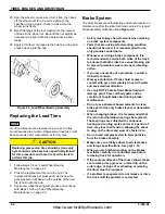
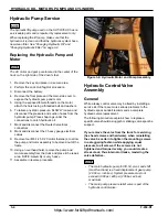
8. The hydraulic reservoir drain plug is located in the

right side of the truck, as shown in figure 3-1 photo.

9.

Slide a flat collection pan, (minimum 10 gallons - 40
liters) under the drain plug, then remove the plug.

10. Change the hydraulic filter. See “Change the

Hydraulic Oil Filter”.

11. Clean the magnetic trap on the drain plug of any

contaminants. When the tank is empty, clean and
reinstall the drain plug.

12. Add hydraulic oil. See page 1-12 for recommended

lubricants. DO NOT overfill.

13. Replace the fill/cap, turn clockwise and make sure it

is tightened securely.

14. Make sure the drain plug is tight enough to prevent

oil leaks, but do not over tighten.

15. Run lift to check for leaks.

16. With the lift OFF and the forks down, check the oil

level on the dipstick and add oil accordingly.

Figure 3-1: Hydraulic Tank Drain

Change the Hydraulic Oil Filter

CAUTION

1.

Park the truck on a level, designated service area
and block the wheels.

2.

Set the key to OFF, remove the key from the key
switch and place in
a secure area.

3.

Perform Lock
Out/Tag Out
procedure.

4.

Disconnect the
battery.

5.

Remove the access
cover.

6.

Using a clean,
lint-free cloth, clean
the area around the
filter element
housing.

7.

Unscrew oil filter cap and pull the filter element from
the tank.

8.

Install the new filter element and tighten fill cap.

9.

Operate the hydraulic system by running the mast
functions and observe the filter for oil leaks.

10. Reinstall the access cover.

After prolonged truck use, hydraulic oil will be
hot and can burn human skin. Allow hydraulic oil
to cool before performing this procedure.

https://www.forkliftpdfmanuals.com/

Summary of Contents for Drexel SLT30 AC

Page 1: ...F 459 R1 LANDOLL CORPORATION 1900 North Street Marysville Kansas 66508 785 562 5381 800 428 5655 WWW LANDOLL COM Model SLT30 35 AC Maintenance Manual https www forkliftpdfmanuals com...

Page 2: ...https www forkliftpdfmanuals com...

Page 3: ...4 Towing the Truck 1 5 General Safety Tips 1 5 Towing Vehicle Requirements 1 5 Towing a Truck in the Reverse Direction 1 5 Lifting and Blocking the Truck 1 5 Cleaning the truck 1 6 Maintenance Introdu...

Page 4: ...Brake Linkage 2 10 Replacing the linear pot 2 10 Master Cylinder 2 10 Replacing Master Cylinder 2 10 Bench Bleed the Master Cylinder 2 11 Check Master Cylinder Fluid Level 2 11 Bleeding Brakes 2 12 Se...

Page 5: ...em Steering Column Dash Assembly 4 1 Removing the Display Panel 4 1 Key Switch 4 1 Steering Wheel Removal 4 2 Steering Column Console Removal 4 2 Steering Torque Feedback Device 4 3 Batteries Care and...

Page 6: ...e Guidance Calibration 5 9 6 Truck Lubrication and Chain Maintenance Lubricating the Truck 6 2 Main Rotation Bearings 6 2 Fork Positioner Lubrication Non Side Shifting Option 6 4 Chain Lubrication 6 5...

Page 7: ...includes operation repair maintenance hydraulic system electrical system and wire guidance Contact your regional Landoll service representative for more information Tools Needed The tools needed will...

Page 8: ...steering warning devices brakes and any attachments if any are used 6 To avoid fire hazards have fire protection equipment present Do not use an open flame to check fluid levels or for leakage of elec...

Page 9: ...n power fuse and install a commercially available Lock Out Tag Out device on the battery connectors Also install a lockout warning reminder on the steering wheel warning that the truck is not availabl...

Page 10: ...e or have an open flame near the battery Gas formed during charging is explosive and can cause injury Consult the charger manufacturer s manual covering your charger for operation and maintenance The...

Page 11: ...evice to these slots 3 Keep towing speed below 2 mph Remember that the person on the towed lift has to turn his head to observe operations Figure 1 2 Forklift Tow Slots 4 To easily disarm the braking...

Page 12: ...compressed air For localized cleaning use a non flammable solvent parts washer and compressed air after the part or area is cleaned Maintenance Introduction Preventative maintenance is an important p...

Page 13: ...INTRO SAFETY INSPECTION AND DASH OPERATIONS 1 7 Operator s Daily Checklist Date Inspector Truck No Model No Location Serial No Shift Hr Meter Hydraulic Oil https www forkliftpdfmanuals com...

Page 14: ...ecks must be done after 50 100 hours of use The To be performed after 250 hrs of truck operation in addition to the required pre shift daily inspection Date Inspector Truck No Model No Location Serial...

Page 15: ...tions Dash Display Check BDI hourmeter Parking Brake Check for function Service Brake Check for leaks shoe wear Hydraulic Fluid Level Check and fill Exterior of Hydraulic Tank Tank Breather Clean Lift...

Page 16: ...icable Forks Top Clip Retaining Pin Function condition Load Rollers No greater than 1 16 movement Steering Operation Functions smoothly Brake Fluid Check Level Hydraulic Oil Filter Change element Batt...

Page 17: ...hains Check Date Inspector Truck No Model No Location Serial No Shift Hr Meter Battery Fluid Hydraulic Oil Technicians 2000 Hour Checklist Action Needed Status Landoll Drexel IC SAFETY OPERATIONAL CHE...

Page 18: ...Apply to splines Carriage Slide Pads Gredag 741 or AeroShell 33MS Brush on slide pads Failure to refill with oil that meets ISO 4406 cleanliness code 15 31 11 may void the warranty Typical NEW oil DO...

Page 19: ...100 1 2 20 40 50 65 81 90 112 9 16 12 55 62 80 100 110 137 9 16 18 60 75 90 112 130 162 5 8 11 75 94 110 137 170 212 5 8 18 85 106 130 162 180 225 3 4 10 130 162 200 250 280 350 3 4 16 150 188 220 27...

Page 20: ...acturer Thick nuts must be used on grade 8 capscrews Use value in if using prevailing torque nuts Dash Size 37 Deg JIC O ring ORS O ring boss 4 11 13 15 17 13 15 5 14 16 21 23 6 20 22 34 36 25 29 8 43...

Page 21: ...loor plate 6 Assemble in reverse procedure Figure 2 1 Floor Plate Assembly Tire Inspection WARNING IMPORTANT It is recommended to replace worn front tires in pairs Careful driving habits add additiona...

Page 22: ...teel band cutting the rubber just above the base band 2 Check that the tires remain centered on the wheels to prevent splitting of the base band and tread separation 3 Correct such defects as soon as...

Page 23: ...from the hub 10 Carefully inspect the bearings for cracks heat discoloration worn rollers etc Check the bearing race for wear and or damage 11 If bearings need to be replaced use a punch or wood block...

Page 24: ...ever servicing a brake component it is recommended to service both sides of the truck to ensure that both sides have equal braking and to prevent premature wear and uneven braking action If you are un...

Page 25: ...than 1 2 12 7 mm is available adjust or check the shoes for wear and replace as needed Brake Adjustment 1 Remove the ignition key and place in a secure area 2 Perform a Lock Out Tag Out procedure 3 Ja...

Page 26: ...ly returned retracted before the wheel can be removed This involves loosening the star adjusters which is done through the access holes in the wheel hub Brake fluid will damage paint Have a container...

Page 27: ...late 13 Reinstall wheel assembly by following steps 19 23 on Load Wheel Bearing Maintenance on page 2 3 14 Pump the brakes several times to seat the new brake shoes 15 Using the brake pedal make a few...

Page 28: ...it towards the loosened nut 6 Repeatedly hit the drum evenly in a circular motion until it pops free then remove the nut 7 Remove the drum and tire assembly NOTE Brake drum wheel assemblies are heavy...

Page 29: ...e park brake onto the mounting plate using the three socket head cap screws 5 Using a feeler gauge leave a gap of 034 86mm between the mounting plate and brake case Loosen the three hex bolts and adju...

Page 30: ...pedal begins its downward stroke Service Brake Linkage NOTE The linkage between the brake pedal and the master cylinder is not adjustable Some other areas that can affect the braking system include L...

Page 31: ...bled See Bench Bleed the Master Cylinder See Figure 2 9 14 Install the new master cylinder in reverse order NOTE Since high pressure is not involved in the bench bleed procedure your finger can be use...

Page 32: ...the key from the key switch and put in a secure place 2 Apply the parking brake perform a Lock Out Tag Out procedure and disconnect the battery 3 Block the wheels so that the truck can t move 4 Start...

Page 33: ...e raised and supported spin the drive wheel and check for noise rolling resistance and free play 2 Rock the wheel in and out on the gearbox If there is any noticeable movement the gearbox must be chec...

Page 34: ...earbox Replacement To repair and or replace the traction motor 1 Set the key switch to OFF Remove the key from the key switch and place in a secure area 2 Disconnect the battery 3 Perform a LockOut Ta...

Page 35: ...tion of Steering and Throttle Pot starting on page 5 9 to re calibrate the accelerator module Replacing Accelerator Module 1 Set the key switch to OFF remove the key from the key switch and put it in...

Page 36: ...2 16 F 459 R1 TIRES BRAKES AND DRIVETRAIN Table provided for general use NOTES https www forkliftpdfmanuals com...

Page 37: ...tings Hydraulic Fluid Check fluid level and look for air bubbles Check the filter See Change the Hydraulic Oil Filter on page 3 2 Other Hydraulic System Components Visually check other components to s...

Page 38: ...ns 40 liters under the drain plug then remove the plug 10 Change the hydraulic filter See Change the Hydraulic Oil Filter 11 Clean the magnetic trap on the drain plug of any contaminants When the tank...

Page 39: ...ing while the truck is running To check or set the pressure you must pull the tilt lever to dead head bottomed out allowing the cylinder to build pressure then set the relief valve 5 Loosen the relief...

Page 40: ...ove four M8 1 25 X 20 motor fasteners to allow the pump and motor assembly to be moved out of the frame 10 Using an overhead hoist remove the pump and motor assembly from the truck and place it the re...

Page 41: ...he top cross members of the mast so the mast sections cannot move Mast Removal Precautions 1 Move the truck to a level designated area 2 Remove the key and place it in a secure place 3 Perform the Loc...

Page 42: ...truck on a level flat surface Clear area around the truck 2 Check hydraulic fluid level 3 Turn the key switch to the ON RUN position 4 Make sure your right foot is on the floor of the operator s compa...

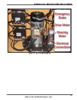
Page 43: ...HYDRAULIC OIL MOTORS PUMPS AND CYLINDERS 3 7 Figure 3 6 Drive and Steering Motor https www forkliftpdfmanuals com...

Page 44: ...3 8 F 459 R1 HYDRAULIC OIL MOTORS PUMPS AND CYLINDERS Table for your general use with this manual NOTES https www forkliftpdfmanuals com...

Page 45: ...rder Figure 4 1 Dash Console Assembly Key Switch 1 Set the key switch to OFF and remove the key from the key switch 2 Perform a Lock Out Tag Out procedure and disconnect the battery 3 Make sure all th...

Page 46: ...port 1 Remove the lower dash cover 2 Pry up the bellows rubber boot free from the bellows retainer plate This exposes the mounting plate for the steering column and the TFD Torque Feedback Device Four...

Page 47: ...For increased battery life reference Battery Care on page 1 4 and check the specific gravity readings daily Since the water must be mixed with the electrolyte for an accurate reading do not check the...

Page 48: ...and that the controls are in the off position Make sure the battery terminals and cables are cleaned of corrosion regularly Clean battery terminals are important not only to the operation of the lift...

Page 49: ...direction control lever to FORWARD 3 Slowly move the truck forward then stop by using the service brake 4 Turn the key switch OFF then back on again 5 Press on the accelerator pedal 6 The truck must...

Page 50: ...ng the preceding steps 5 Connect the battery and test the horn Seat Switch Assembly The driver s seat micro switch and cable assembly are mounted to the bottom of the seat cushion Check Driver s Seat...

Page 51: ...are to avoid breaking the LED assembly 5 Disconnect the wire connector and remove the bracket that is attached to the overhead guard 6 If shielding or guard covers are involved make certain that the g...

Page 52: ...T30 35 AC System and Controller fuses See Figure 4 9 The fuse box is located in the back compartment on the right side Exact size and amperage rating must but be retained when replacing Figure 4 9 Fus...

Page 53: ...wn the main dash display for reference Figure 5 1 Headlights and Menu Buttons 1 Headlight Key Press this button to turn the headlights on if equipped Once the headlights are on press and hold the butt...

Page 54: ...u have correctly entered the truck password you will enter the dash display menu This is where you can access and program the truck s many feedback devices and parameters Below is shown the main dash...

Page 55: ...elow is a list of possible icons and their functions When this icon appears next to the button pressing the button will allow you to exit the menu and return to the dash display main screen When this...

Page 56: ...urrent 0 100 Seat Switch On Off 0 1 Battery Rollout Switch On Off 0 1 JS Forward Switch On Off 0 1 JS Reverse Switch On Off 0 1 JS Horn Switch On Off 0 1 JS WGU Switch On Off 0 1 JS Aux Switch On Off...

Page 57: ...1000 200 Sets the resolution of the steering wheel at high speeds Lift Lockout 0 30 25 Sets the BDI for the truck to go into lift lockout mode Seat Timer 1 Sec 0 30 30 Sets the time delay that is allo...

Page 58: ...ts the maximum acceleration percentage for mode 1 M1 Neutral Braking 0 100 20 Sets the maximum regenerative braking percentage for mode 1 M1 Max Speed 0 100 100 Sets the maximum truck speed percentage...

Page 59: ...Max Lift Speed 0 100 100 Sets the maximum lift speed percentage for mode 2 M2 Max Tilt Speed 0 100 65 Sets the maximum tilt speed percentage for mode 2 M2 Side Shift Speed 0 100 80 Sets the maximum si...

Page 60: ...ge Add 5 to this value to get the Brake Pot High value 7 Press the button with the icon shown below next to it to exit the No Run Diagnostic submenu and return the main menu 8 In the main menu use the...

Page 61: ...le buttons on either side of the display screen until the screen says WIRE CAL 4 Drive the truck completely across the wire at the 45 angle 5 Approximately 5 seconds after the rear antenna has cleared...

Page 62: ...raction Motor Temp Warning Traction motor temperature is above the high warning setpoint Bring the traction motor temperature below the high warning setpoint If the temperature continues to rise an er...

Page 63: ...e is not properly installed The battery gate switch is not connected to the truck harness Insure battery gate is installed properly Check the battery gate switch plug to see if it is connected to the...

Page 64: ...rature is at or above the programmed high temperature setpoint Bring the traction motor temperature below the high temperature setpoint and cycle the key switch 104 Hi Traction Drive Temp Traction con...

Page 65: ...nt Excessive load on vehicle Improper mounting of pump controller Bring pump controller temperature below the high temperature setpoint Reduce load on vehicle Check to see if pump controller is proper...

Page 66: ...144 Steer Hi Drive Temp Steer controller temperature is at or above a programmed high temp setpoint Excessive load on vehicle Improper mounting of steer controller Bring steer controller temperature b...

Page 67: ...150 Steer Pot Sensor Fault Prox switch is not connected to the truck harness Faulty prox switch Check to see if prox switch is connected to the truck harness Replace prox switch 166 WGU Comm Fault WG...

Page 68: ...5 16 F 459 R1 DREXEL SLT30 35 AC CALIBRATION PROGRAMMING Table provided for general use NOTES https www forkliftpdfmanuals com...

Page 69: ...DREXEL SLT30 35 AC CALIBRATION PROGRAMMING 5 17 https www forkliftpdfmanuals com...

Page 70: ...5 18 F 459 R1 DREXEL SLT30 35 AC CALIBRATION PROGRAMMING https www forkliftpdfmanuals com...

Page 71: ...F 459 R1 6 1 Chapter 6 Truck Lubrication and Chain Maintenance Figure 6 1 Grease Locations https www forkliftpdfmanuals com...

Page 72: ...river s compartment 7 See Lubrication Specifications on page 1 14 for recommended lubricants WARNING Main Rotation Bearings 1 Turn the truck off and remove the key and place in a secure area 2 Perform...

Page 73: ...ease the pivot cylinder clevis until fresh grease is squeezed from the clevis Wipe off excess grease See Figure 6 4 5 Grease the shift chain rollers There is one roller on each shift cylinder You can...

Page 74: ...ft and right 2 times and wipe up excess grease 10 Note For optimum performance lubricate shift bearing pads daily for the first 50 100 hours of truck operation Figure 6 8 Shift Bearing Pads Fork Posit...

Page 75: ...replaced in pairs Chain stretch can be measured with a chain wear scale See Figure 6 10 The scale indicates whether the distance between two chain links is within tolerance The shaded area in the ill...

Page 76: ...der clevis 8 Place the tilt gauge against the rear outer mast rail on the right side of the truck about 6 152 mm above the mast cross member See Figure 6 11 CAUTION 9 Relieve the hydraulic pressure on...

Page 77: ...rhead crane rated at 6 000 or higher to the mast and lift slightly 6 Disconnect the two tilt cylinders See Removing the Tilt Cylinders on page 6 7 Steel toed shoes and eye protection are required when...

Page 78: ...ength is adjusted by turning on the cylinder shaft with an open end wrench Figure 6 14 Pivot Adjustment and Lock Bolt 3 Pivot the mast 90 to the right 4 With the mast at 90 from the truck frame move t...

Page 79: ...the way to the right The full travel length right to left should be set at 20 See Figure 6 17 This rear side shift cylinder is adjusted to achieve this travel by adjusting the length of the chain See...

Page 80: ...6 10 F 459 R1 TRUCK LUBRICATION AND CHAIN MAINTENANCE Table for your general use with this manual NOTES https www forkliftpdfmanuals com...

Page 81: ...Document Control Revision Log Date Revision Improvement s Description and Comments 05 26 15 F 459 R1 Initial Release 10 31 16 F 459 R1 Hydraulic fluid changes Joshua https www forkliftpdfmanuals com...

Page 82: ...Model SLT30 AC Maintenance Manual Re Order Part Number F 459 R1 LANDOLL CORPORATION 1900 North Street Marysville Kansas 66508 785 562 5381 800 428 5655 WWW LANDOLL COM F 459 R1 Copyright 2016 Landoll...

Reviews: