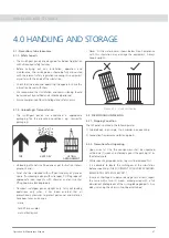
Operation & Maintenance Manual
11
INSTALLATION
5.0 INSTALLATION
5.1 - Checks Prior to Installation
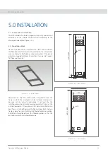
Check the order of cubicle arrangement, quantity and external
dimensions of the cubicle and base frame according to the
drawing provided (Refer gure 5.2 a).
5.2 - Foundation Work
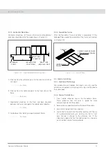
Hack out the oor cement surface out to a level of 50mm below
the oor level. The framework is then seated on the sunken oor
and is anchored to the oor by angle iron brackets. If the panels
are factory coupled with base frames then it can be also xed on
at oor and channels.
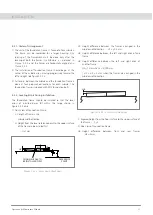
Adjustment on the M12 anchor bolts is required to level the
frame on which the switchgear is to be installed. Leveling must
be done with an accurate level gauge. If not level, the GIS
switchboard may be distorted, leading to eventual failure of the
installed equipment. Please ensure that panel base frame and
base frame in nished oor level shall be matched. Both the base
frame or base frame and channel shall be bolted or tag welded.
Installation should be done in the following order so that the
level errors are within an allowable range.
Figure 5.2 a - Base Frame
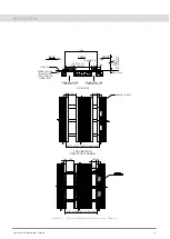
Figure 5.2 c - Base Frame
Figure 5.2 b - Base Frame
1600 / 1800
400
233
4 : M12
115
52
52
40
140
593
233
4 : M12
52
52
40
140
1600 / 1800
11
5

