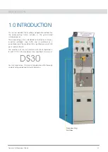
background image

Operation & Maintenance Manual

OPERATION AND MAINTENANCE MANUAL

TYPE GIS DISCONNECTING SWITCH

Introduction, Speci cations, Disconnecting Switch,
Operating Mechanism, Interlock Features
Maintenance & Inspection Criteria and Standard
Accessories

Summary of Contents for GIS DS30 1250A

Page 1: ...OPERATION MAINTENANCE MANUAL TYPE GIS 36 kV CUBICLE ...

Page 2: ...NDATION WORK CUBICLE INSTALLATION CONNECTING CONTROL WIRING CONNECTING POWER CABLE INSPECTION AFTER INSTALLATION COMMISSIONING TESTING PRELIMINARY CHECKS TESTING START UP SWITCHING OPERATIONS SAFETY INTERLOCKS IN GIS SWITCHGEARS MAINTENANCE AND INSPECTION FUNDAMENTAL PHILOSOPHY OF MAINTENANCE AND INSPECTION CLASSIFICATION OF MAINTENANCE AND INSPECTION 4 0 5 0 6 0 7 0 4 1 4 2 4 3 4 4 5 1 5 2 5 3 5 ...

Page 3: ...r and its standard handling procedures This metalclad SF6 Gas Insulated Switchgear GV3N with all its devices housed within a compact cubicle and gas sealed is a type tested indoor cubicle for rated voltages up to 36kV GV3N The cubicle is tted with a vacuum circuit breaker for single busbar system The insulating medium is SF6 subjected to a minimum pressure ...

Page 4: ...rcuit Making Current Rated short circuit symmetric breaking Current Rated Lighting Impulse Voltage 1 2 50 Micro Sec Rated A C 1 min pf voltage Width Depth Height A Hz kA 3sec kAp kA kVp kV rms mm mm mm 36 50 60 630 1250 2000 2500 26 3 31 5 63 80 26 3 31 5 170 70 600 1600 2500 600 1600 2500 800 1600 2500 800 1600 2500 2 3 Normal Service Conditions for Indoor Switchgear 1 Ambient air temperature 10 ...

Page 5: ... CONTACTS 1 CONTACT FOR ALARM 1 CONTACT FOR TRIP 2 VIEWING WINDOW FOR DISCONNECTOR SWITCH 3 HANDLE FOR METERING COMPARTMENT 4 BREAKER COMPARTMENT SF6 GAS PRESSURE MONITORING DEVICE WITH 2 CONTACTS 1 CONTACT FOR ALARM 1 CONTACT FOR TRIP 5 HANDLE FOR VCB DS COMPARTMENT 6 VIEWING WINDOW FOR BREAKER STATUS INDICATIONS 7 HANDLE FOR CABLE COMPARTMENT 8 HOLE FOR ROUTING INTERPANEL WIRES 9 BUS BAR DS GAS ...

Page 6: ... MONITORING DEVICE 6 VIEWING WINDOW FOR BREAKER STATUS 7 HOLE FOR ROUTING INTER PANEL WIRES 8 BUSBAR DISCONNECTOR SWITCH COMPARTMENT 9 DUCT FOR HOT GAS 10 REAR COVER 11 PRESSURE RELIEF FLAP 12 POWER CABLE ADAPTER 13 POWER CABLE NOT IN E A SCOPE OF SUPPLY 14 BASE FRAME 15 CURRENT TRANSFORMER 16 BURSTING DISK 17 EARTH BAR 18 COPPER BUSBAR Figure 3 2 2 Sectional View of Outgoing Feeder Panel FINISH F...

Page 7: ...two contacts shall be open 1 When gas pressure decreases to less than 1 25 Kg cm contact with terminal no 3 4 becomes Close This contact can be used to give an alarm so that gas can be re lled before gas pressure falls to minimum permissible pressure When the gas is re lled and the internal pressure exceeds 1 25 Kg cm then the switch is automatically reset becomes open 2 When gas pressure decrease...

Page 8: ... lled in the panel to check if the weld has removed the leakage and there is no further leakage after which the SF6 gas is lled in the equipment at a desired pressure of 1 35 bar The detailed procedure for Vacuuming and Gas lling is provided in Annexure A After the gas lling is completed the Power Frequency Withstand Test should be done at sight Note For quality and purity of SF6 gas refer the qua...

Page 9: ...shackles and ensure that lifting hooks are locked properly Transport switchgear panels upright only Carry out loading operations only when it has been ensured that all precautionary measures to protect personnel and materials have been taken and using a crane fork lift truck and or manual trolley jack Never tilt the crates over as shown below Non Compliance with this stipulation may damage the equ...

Page 10: ...ok should not be more than 120 degrees Rope with appropriate strength to be used 2 When the equipment is hauled on manual lifting truck be sure that the pallet is of suf cient loading capacity Furthermore do not lower the cubicle on its edge as this may result in mechanical damage The cubicle is provided with a transportation channel base to accommodate the fork of the pallet truck 3 Rollers may b...

Page 11: ...ell ventilated environment The storage area must shelter the equipment from deterioration by agents like Water Water Vapour Salt Laden air Pollution of any type Micro organisms Store switchgear panels standing upright Do not stack switchgear panels Switchgear panels are not weather proof and should not be left outdoor where rain and moisture may cause irreparable damages For temporary indoor stora...

Page 12: ...ked slightly dilute the dry greases with neutral paraffin oil 10 12 times manoeuvres should be carried out in order to check the mechanical operation of the equipment The minimum threshold 85 of Un of the coil electrical operation should be tested X X X X X X X X X 1 2 3 4 4 3 Special Instruction for a storage between 6 and 12 months period 4 4 4 Special Instructions for a storage period between 1...

Page 13: ...ed on at oor and channels Adjustment on the M12 anchor bolts is required to level the frame on which the switchgear is to be installed Leveling must be done with an accurate level gauge If not level the GIS switchboard may be distorted leading to eventual failure of the installed equipment Please ensure that panel base frame and base frame in nished oor level shall be matched Both the base frame o...

Page 14: ... 600 600 REAR PANEL FIN FL LVL CEMENT FILLING FOR LEVELING WITH FINISHED FLOOR LEVEL 1400 350 200 100 52 74 75 X 125 X 6 EDGE ANGLE 50 X 100 X 6 ISMC PANEL ALONGWITH BASE FRAME FRONT FIN FL LVL FLOOR OPNG FOR CONTROL CABLE FLOOR OPNG FOR POWER CABLE SIDE VIEW TOP VIEW WITH ONLY CROSS CHANNEL INSTALLATION Figure 5 2 c Top view with panel on Frame Cross Channel ...

Page 15: ...e foundation frame should be installed so that the level errors of installed bases fall within the range shown in gure 5 2 2 a b 1 Front View of Foundation Frame L Length of frame in the cubicle width direction H Height from the level reference point to the upper surface of the frame to be installed rst H 1mm Figure 5 2 2 a Level errors front view REFERENCE POINT CHANNEL BASE TO BE INSTALLED FIRST...

Page 16: ...e 5 2 4 5 3 Cubicle Installation 5 3 1 Location of Fastenings GIS is divided into unit cubicles Parts bolts nuts etc used for installation are packed in a vinyl bag with a tag and attached to the cubicle body 5 3 2 Order of Installation 1 Draw cubicle reference line on the foundation frame These reference lines will serve a guide for more accurate alignment of the cubicle 2 Remove the transportati...

Page 17: ...1 Handling of components without hand gloves 2 Misalignment of bushings busbar 3 Using additional force during coupling use only lead screw or hydraulic jack as mentioned in O M manual 4 After applying MOLYKOT 111 Compound FOMBLIN GRM60 to silicon plug Don t Keep open to atmosphere more than half an hour 5 Fix B B Plug in conductor main with the panel during panel movement 6 Leave the B B Plug in ...

Page 18: ... position of the power cable and mount the cable gland plates onto the welded studs at the cubicle base plate Tighten the nuts securely e If there is any gap between the power cables to ll the gap with sealing compound f The Cable screen should be properly connected to the panel earthing Note Connect only one end of the cable earth and not both For single core cables there should be a gap between ...

Page 19: ...gnals and indicators 5 Watch for any abnormalities 6 4 SWITCHING OPERATIONS 6 4 1 POSITION ISOLATION The 3 position disconnecting switch selects one of three positions ON OFF and Earth by a pair of blades The cable side may be earthed through the circuit breaker It can be electrically and mechanically interlocked with an associated circuit breaker For details refer to the relevant instruction manu...

Page 20: ...can t be operated either mechanically or electrically when Isolator is accessed 2 Permissive Earth Feeder Bus Coupler Riser Premissive Earth PE 1 In normal condition key will not be available in PE lock 2 To operate DS from OFF to Earth position key has to be trapped in PE lock 3 Key will be trapped in lock till DS is in Earth position Sequence of operation for BUS A Earthing 1 To Earth power cabl...

Page 21: ...ccess cover is OPEN Padlocking Facility 1 Metering DS mechanism compartment door handle 2 VCB compartment door handle 3 Aux front cable entry compartment door handle 4 DS operating hole pad loack Visual Indications 1 ON OFF status of VCB 2 ON OFF EARTH status of Disconnector Switch 3 Operation counter 5digit on VCB front facia 4 Spring Charged Discharged indication ag on VCB front facia 5 SF6 Gas ...

Page 22: ... Q1 Q2 STEP 2 BUS Q0 Q1 Q2 STEP 3 BUS Q0 Q1 Q2 STEP 4 BUS Q0 Q1 Q2 1 SWITCHING VCB INITIAL STATUS Q1 OFF Q0 OFF Q2 OFF CONNECTING CABLE TO EARTH BUS Q1 OFF Q0 OFF Q1 OFF Q0 OFF to ON Q2 OFF to ON Q2 ON DISCONNECTING CABLE FROM EARTH BUS Q1 OFF Q0 OFF Q2 ON Q2 ON to OFF Q1 OFF Q0 ON to OFF SWITCHING SEQUENCE STEP 0 BUS Q0 Q1 Q2 STEP 1 BUS Q0 Q1 Q2 STEP 2 BUS Q0 Q1 Q2 STEP 3 BUS Q0 Q1 Q2 STEP 4 BUS ...

Page 23: ...nce is standard operating sequence If any key interlocks key exchange are provided please refer key interlock arrangement provided by Design SWITCHING SEQUENCE INITIAL STATUS Q1 OFF Q0 OFF Q2 OFF CONNECTING BUSBAR TO EARTHING Q1 OFF to ON Q4 OFF to ON Q1 ON Q4 ON Q0 OFF Q0 OFF to ON DISCONNECTING BUSBAR FROM EARTHING Q1 ON to OFF Q4 ON to OFF Q0 ON toOFF Q0 OFF Q1 ON Q4 ON STEP 0 Q4 OFF Q3 OFF Q2 ...

Page 24: ...are provided please refer key interlock arrangement provided by Design INITIAL STATUS Q1 OFF Q0 OFF Q2 OFF CONNECTING BUSBAR TO EARTHING Q1 OFF to ON Q3 OFF to ON Q1 ON Q3 ON Q0 OFF Q0 OFF to ON DISCONNECTING BUSBAR FROM EARTHING Q1 ON to OFF Q3 ON to OFF Q0 ON toOFF Q0 OFF Q1 ON Q3 ON STEP 0 Q4 OFF Q3 OFF Q4 OFF Q4 OFF Q2 OFF Q2 OFF Q4 OFF Q2 OFF Q2 OFF Q4 OFF STEP 1 STEP 2 STEP 3 STEP 4 BUS A Q1...

Page 25: ...sequence is standard operating sequence If any key interlocks key exchange are provided please refer key interlock arrangement provided by Design SWITCHING SEQUENCE INITIAL STATUS Q1 OFF Q0 OFF Q2 OFF CONNECTING BUSBAR TO EARTHING Q2 OFF to ON Q4 OFF to ON Q2 ON Q4 ON Q0 OFF Q0 OFF to ON DISCONNECTING BUSBAR FROM EARTHING Q2 ON to OFF Q4 ON to OFF Q0 ON toOFF Q0 OFF Q2 ON Q4 ON STEP 0 Q4 OFF Q3 OF...

Page 26: ...mage of gas piping Gas pressure Monitor indication if Monitor is provided Operating devices Cleaning oiling and greasing Facility as a whole Facility as a whole Circuit breaker Tightness of terminals of low voltage circuit wiring Conduction of auxiliary switches Tightness of bolts and nuts Internal check of operation mechanisms During patrol During patrol During patrol Once every 3 years During pa...

Page 27: ...ection should be performed 7 2 Classi cation of Maintenance and Inspection 1 Routine Patrol Inspection This inspection is performed externally while the panel is in operation such as voltage and current readings and any deviation from normal conditions This inspection is part of the routine patrol on the facility as a whole 2 Periodically Inspection Ordinary and Detailed This inspection is perform...

Page 28: ...ance Manual OPERATION AND MAINTENANCE MANUAL TYPE GIS DISCONNECTING SWITCH Introduction Speci cations Disconnecting Switch Operating Mechanism Interlock Features Maintenance Inspection Criteria and Standard Accessories ...

Page 29: ... EXTERNAL VIEW FACIA OF DISCONNECTING SWITCH POSITION OF SWITCH BLADES OPERATING MECHANISM ELECTRICAL OPERATION MANUAL OPERATION EMERGENCY OPERATION INTERLOCK FEATURES STANDARD WIRING DIAGRAM MAINTENANCE INSPECTION CRITERIA INSPECTION SERVICING CRITERIA CONTENTS OF INSPECTION CHECK POINTS FOR MAINTENANCE INSPECTION STANDARD ACCESSORIES MANUAL OPERATING HANDLE 01 02 02 02 03 03 03 04 05 05 06 06 06...

Page 30: ...ted for installation in the gas insulated switchgear type GV3N and its performance is guaranteed under the condition that a speci ed pressure of SF6 gas is sealed in the GIS The conditions of use shall conform with those stipulated in IEC 62271 102 Other conditions are as speci ed in this manual DS30 For safe long service this manual should be read for thorough understanding and be kept for quick ...

Page 31: ...ATIONS 2000A 1250A 630A kV Rated Current Rated Frequency Rated Short Time Current Rated short circuit Making Current Rated short circuit symmetric breaking Current Rated Lighting Impulse Voltage 1 2 50 Micro Sec Rated a c 1 min pf voltage A Hz kA 3sec kAp kA kVp kV rms 36 50 630 1250 2000 2500 26 3 31 5 63 80 26 3 31 5 170 70 SF6 Gas Sealing Pressure kg cm 0 abS 20 C 1 35 Operating method Motor sp...

Page 32: ...evice is transferred through the connecting shaft to the rod and blade As the shaft rotates the insulating rod drives the blade to select xed contacts and the drive link are located inside a gas compartment The operation can be performed by both the motor spring drive CLOSE OPEN or manual spring drive CLOSE OPEN EARTH one of three positions CLOSED OPEN OR EARTHED The gas sealing of the drive rod i...

Page 33: ...s The contacts are made of drawn copper conductors Earth contacts are connected to the cubicle framework In the CLOSE operation the blades connect the breaker to the busbar Whilst in OPEN operation the blades are isolated from the breaker and earth For EARTH operation the moving contacts connect breaker to the earth contacts mounted on the disconnect switch frame Figure 3 1 2 b DS in CLOSE Positio...

Page 34: ...perating Mechanism shaft charging the closing spring Towards the end of the operation the closing spring will be released and this released energy drives the mechanism to rotate at high speed This mechanism is connected to DS main shaft through a gas tight coupling The driving force from the mechanism rotates the main DS shaft which in turn moves the contact blades At the end of the operation the ...

Page 35: ...et for the next motor operation Rotate the shutter knob anticlockwise to remove the operating Caution Before Manual Operation 1 Do not attempt to operate the Disconnecting switch if the circuit breaker is in closed position 2 When the circuit breaker is in CLOSED position interlocks prevents the shutter from being opened 3 Do not operate DS manually in open door condition Figure 3 2 2 a DS FACIA h...

Page 36: ...Q 10 K10 17 L4B K8 8 5 12 K1 1 3 K3 7 10 15 K4 4 2 K2 3 XK1 XH1 XH1 XH1 XK1 XK1 XH1 XK1 XK2 XH2 K6 6 L8 C L8 17 XH2 XH2 XK2 C1 20 L7B L5 12 61 L9 23 c1 c2 25 c4 27 29 c6 31 b1 b2 b3 33 35 b4 37 39 b5 41 b6 43 b7 45 a1 a2 47 49 a3 a4 51 53 a5 55 a6 a7 57 59 ab8 CIRCUIT CLOSING OPENING CIRCUIT 5 K5 14 D5 9 K9 K11 XQ 11 DS WITH E SW DS IN PROGRESS 6 L4A 13 16 L4A NO L4 L4B NC R1 R1 R2 D1 SHUTTER INTE...

Page 37: ...d Servicing Criteria The inspection intervals should be shortened for equipment used in adverse conditions 4 0 MAINTENANCE INSPECTION CRITERIA 4 2 Contents of Inspection Check points in visual ordinary and detailed inspection are listed in table 4 1 Table 4 1 Inspection Intervals 1 Visual inspection 2 Ordinary inspection 3 Detailed inspection and major service Arbitrary time Performed every 3 year...

Page 38: ... of link Greasing state in sliding and rotating parts Warping or galling of parts Oiling machine oil state in sliding and rotating parts Remove old grease and apply new grease Lubrication and operation Oiling and greasing Check for dislocated connectors and pins and for deformation and breaks Check for loose fastenings of the switch terminals and for rust Contact state of auxiliary switches Visual...

Page 39: ...STANDARD ACCESSORIES Operation Maintenance Manual 10 5 1 Manual Operating Handle 5 0 STANDARD ACCESSORIES Figure 5 1 Manual Operation Handle ...

Page 40: ...Operation Maintenance Manual OPERATION AND MAINTENANCE MANUAL TYPE GIS BREAKER GV3N Introduction Speci cations VCB Maintenance and Standard Accessories ...

Page 41: ...BREAKER OPERATING MECHANISM MOTOR CHARGING MECHANISM MANUAL EMERGENCY CHARGING CLOSING OPENING OPERATION OF CONTROL CIRCUIT CLOSING SPRING CHARGING OPERATION OPENING OPERATION FIGURES STANDARD WIRING DIAGRAM MAINTENANCE INSPECTION SERVICING CRITERIA CONTENTS OF INSPECTION STANDARD ACCESSORIES MANUAL CHARGING HANDLE MANDATORY SPARES 01 02 02 02 03 03 03 03 03 03 03 03 04 04 04 04 04 06 07 07 07 08 ...

Page 42: ...s performance is guaranteed under the condition that a speci ed pressure of SF6 gas is maintained in the GIS The circuit breakers conform to IEC 62271 100 within the parameters of their technical data GV3N CB The type GV3N CB are not only suitable for frequent switching under normal load conditions but are also capable of a large number of short circuit breaking operations within the restrictions ...

Page 43: ...ke time Typical opening time at minimum volts Spring motor charging time Electrical Characteristics Rated Voltage 2500A 2000A 1250A 630A kV Rated Current Rated Frequency Rated Short Time Current Rated short circuit Making Current Rated short circuit symmetric breaking Current Rated Lighting Impulse Voltage 1 2 50 Micro Sec Rated a c 1 min pf voltage A Hz kA 3sec kAp kA kVp kV rms 36 50 630 1250 20...

Page 44: ...is is the point of contact separation and from this point the momentum and the continuing action of the opening springs alone pull the coupling rods and thus the interrupter contacts to the fully open position 3 0 VACUUM CIRCUIT BREAKER 3 2 Vacuum Circuit Breaker Operating Mechanism The mechanism is of the stored energy motor wound or manually charged spring operated type It is suitable for auto r...

Page 45: ...time 10secs During this closing operation the b contact of the auxiliary switch is turned off and also the energised relay Y opens it contact Yb to complete the pumping prevention circuit Thus if the same close signal stays on Yb remains open and prevents reclosing of the circuit breaker The closing circuit is also provided with contact Xb from the control relay which prevents the spring release c...

Page 46: ...BREAKER Operation Maintenance Manual 05 Figure 3 3 4 shows the front view of the operation mechanism with the front fascia of the Circuit breaker mechanism removed Figure 3 3 4 a Front View of The Operation Mechanism ...

Page 47: ...B02 B03 B04 B05 a3 a4 a5 b2 b3 b4 b5 a2 a1 A3 A4 A5 B2 B3 B4 B5 K2 HT2 K HT VE VE ON P B ON P B Y TC1 TC2 VE LEGEND DESCRIPTION Y Y b X X a X b TC1 M CC AUX RELAY Y RELAY N C CONTACT CONTROL RELAY X RELAY N O CONTACT X RELAY N C CONTACT CLOSING COIL TRIPPING COIL 1 SPRING CHARGING MOTOR b C a BKR AUX CONTACT N O BKR AUX CONTACT N C CAPACITOR DIODES RESISTORS FUSE LEGEND DESCRIPTION D1 D6 R1 R4 F L...

Page 48: ...ry Detailed Visual check Category Check point Operation Greasing Loose bolts and nuts Dust and foreign matters Dislocated parts Filling and chips Indication of indicator and Counter Deformation damage wear Resetting operation of trip prop and closing prop Movement of rollers and pins Warping or galling of parts Check on reset condition Remove old grease and apply new grease Check for dislocated co...

Page 49: ...STANDARD ACCESSORIES Operation Maintenance Manual 08 5 1 Manual charging handle 5 0 STANDARD ACCESSORIES ...

Page 50: ...UND TYPE SEMAPHORE INDICATOR SHAPE SQUARE TYPE CLOSING COIL TRIPPING COIL INDICATING LAMP MANUAL DS OPERATING HANDLE MANUAL SPRING CHARGING HANDLE ELECTRIC CONTACT GREASE MECHANICAL CONTACT GREASE TOUCHUP PAINT VCB SPRING CHARGING MOTOR DOOR HANDLES 1 2 3 4 5 6 7 8 9 10 11 12 13 14 15 16 17 Unit Nos Nos Nos Nos Nos Nos Nos Nos Nos Set Nos Nos Set Set Set Nos Nos Quantity 2 4 2 2 2 2 2 1 1 1 1 1 1 ...

Page 51: ...n each panel Gas Filling Plug the unit into a suitable power supply Close all valves Make sure the vacuum compressor power switch is OFF Connect one end of equipment hose to the equipment being charged Connect to valve VB for lling gas in VCB compartment and connect to valve VBD for lling gas in Busbar and DS compartment Turn valve V 1 to the Charge position up Turn valve V 2 to the Charge positio...

Page 52: ...eep the vessel you are drawing gas from warm This applies to the onboard tank or external vessel FINISH FLOOR LEVEL FRONT VIEW MANDATORY SPARES Operation Maintenance Manual 11 Figure 1 Showing Arrangement of panels with SF6 gas inlet valve Figure 2 Showing di erent positions on Manometer Figure 2B Figure 2A Figure 2C ...

Page 53: ... XDS Operator panel 1 2 3 4 5 Sl No Mandatory Spares Spares for GAS lling Description SF6 GAS pressure manometer SF6 GAS REFILLING EVACUATING MODEL GFU10 SF6 IR LEAK DETECTOR MODEL GIR 10 SF6 Gas Cylinder Filling adapter Pipe Unit Nos Nos Nos Nos Nos Quantity 1 1 1 1 1 ...

Page 54: ...NOTE Operation Maintenance Manual 13 ...

Page 55: ...NOTE Operation Maintenance Manual 14 ...

Page 56: ...d Dandenong 3175 Melbourne Victoria Australia Tel 613 9706 7288 Email sales tamcoaustralia com au Web www tamcoaustralia com au India Level 2 Unnati Building Automation campus A 600 TTC Industrial area Shill Mahape road Navi Mumbai 400710 Tel 91 22 6722 6926 Fax 91 22 6722 1556 Email ese intl Lntebg com Indonesia PT TAMCO Indonesia F 36 Jalan Jababeka Raya Jababeka Industrial Estate Cikarang Utara...

Reviews: