VACUUM CIRCUIT BREAKER
Operation & Maintenance Manual
03
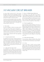
The type GV3N-CB are tested as per IEC. They have been
designed for reliability with minimal maintenance so that there is
no need for access into the SF6 insulated chambers during the
life of the vacuum interrupter. The motor wound stored energy
spring mechanism has been designed with a minimum number
of high quality components in line with this concept.
The mechanism and drive is bolted out side of the circuit breaker
tank and the three pole assemblies are bolted inside SF6 tank.
They are connected via contact wipe springs and coupling rods
through gas tight sealing bushes to the insulators xed to the
vacuum interrupter moving terminals. The sealing ring is
mounted in the brass hub on the tank.
3.1 - Pole Assembly
The vacuum interrupter is xed to its cast resin insulation
supports by a connection plate attached to the xed terminal.
The mechanism end of the assembly is tied together by the
molding mounting plate which located around the seal bush.
The phase assembly is xture built to ensure the correct lineup of
interrupter, current transfer contact from interrupter moving
terminal and the drive through the sealing bush. Thus when an
interrupter reaches the end of its life, the complete pole
assembly is replaced.
3.1.1 - Closing of Interrupter Contacts
The discharging of the mechanism closing spring rotates the
secondary shaft anti-clockwise to push the interrupter contacts
to the contact touch point via the pre-stressed contact spring
and the coupling rods. The coupling rods stop moving at this
point but the mechanism continues to further compress the
contact spring opening up the wipe or snatch gap until the
mechanism latches and the circuit breaker pole is then
considered closed. This closing movement also charges the pre-
loaded opening springs.
3.1.2 - Opening of the Interrupter Contacts
The displacement of the mechanism trip latch allows the
opening springs and the contact springs to rotate the secondary
shaft clockwise until the wipe or snatch gaps are zero. This is the
point of contact separation and from this point the momentum
and the continuing action of the opening springs alone pull the
coupling rods and thus the interrupter contacts to the fully open
position.
3.0 VACUUM CIRCUIT BREAKER
3.2 - Vacuum Circuit Breaker Operating Mechanism
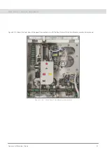
The mechanism is of the stored energy, motor wound or
manually charged spring operated type. It is suitable for auto-
reclosing duties. Basically it comprises a closing spring charging
system and a spring charged latch, a closing cam, the close / trip
latch which is displaced to trip the closed circuit breaker, and the
drive to the poles in the form of the secondary shaft. In addition
there are the spring release solenoid, the trip solenoid, the
auxiliary switches and manual operation On-Off push buttons.
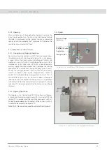
3.2.1 - Motor Charging Mechanism
The closing springs are charged electrically by the motor and
gearbox rotating the mechanism main drive shaft via the pawl
drive arm and ratchet plate. The rollers mounted each side of the
ratchet plate engage with the closing spring latch after passing
through
top dead centre . Reverse movement of the
mechanism shaft is prevented by a clutch mounted in the
mechanism side sheet. The design of the ratchet plate prevents
overcharging by means of a non-toothed area. An additional
cam on the main shaft operates a limit switch which opens the
motor circuit and completes the spring release solenoid circuit.
When the closing spring is discharged, the limit switch condition
is reversed and the motor recharges the closing spring
automatically.
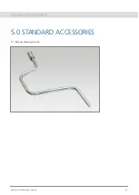
3.2.2 - Manual (emergency) Charging
The closing spring is tensioned manually by tting the hand
crank lever onto the intermediate shaft on the motor gearbox.
This handle is tted with a clutch to prevent reverse movement.
3.2.3 - Closing
When the closing spring is CHARGED and the circuit breaker
indicates Open , the circuit breaker can be closed by either the
electrical release of the closing spring or by the manual close
pushbutton. This causes the main shaft and thus the drive cam
to rotate driving the secondary shaft anti-clockwise via the roller.
When the circuit breaker is fully closed, the close/trip latch
locates behind the roller holding the circuit breaker closed and
indicating Close .

