E1/G.703 F
IBER
O
PTIC
M
ODEM
O
PERATING
M
ANUAL
IOA76-1F
15
May 2009
S
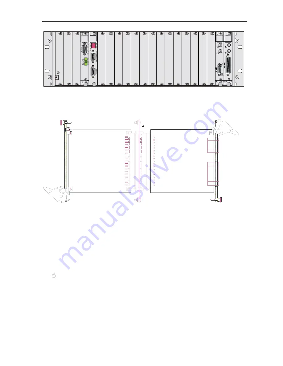
Figure 8.
Installation of the devices in the form of a card in MD-72 telecommunication rack,
rear view.
Figure 9.
Installation of the devices in the form of a card in MD-72 telecommunication rack,
sectional view.
4.3 Power
supply
TM-76 modem can be supplied with 18
÷
60V DC voltage. MD-76 card is supplied with
18
÷
60V DC voltage from TM-72 telecommunication rack. Power supply connection is described
in TM-72 rack operating manual. Power supply voltage parameters are given in paragraph 7.6
The correct power supply of the device is signalized by a light indicator
on the front panel.
18
÷
60V power supply unit voltage should be connected to the socket with external screw
connections. There is no requirement concerning polarity of power supply voltage.
The grounding should be connected to the grounding terminal on the casing. The grounding
cable should have low impedance for high frequencies.
Note.
The device has no built-in disconnecting system, thus an easily accessible
disconnecting system should be mounted into the fixed cabling.
Summary of Contents for MD-76
Page 42: ...E1 G 703 FIBER OPTIC MODEM OPERATING MANUAL IOA76 1F 36 May 2009 Figure 27 G 826 statistics...
Page 54: ......
Page 55: ......

