5
X
RS-232,485 + 2
X
E
THERNET
/2 M
BIT
/
S
G.703 (G.704) M
ULTIPLEXER
O
PERATING
M
ANUAL
IOA81-1E
7
August 2004
2.4
Principles of Connecting
E1 Interface
Input and output signals of the E1/G.703 interface can be fed in two ways:
•
By using two coaxial cables with the impedance of 75
Ω
, terminated with 1,6/5,6 plug-in
connectors, or
•
By using two screened balanced cables with the impedance of 120
Ω
, or one screened
double cable with the same impedance.
Please remember to set jumpers inside the device in accordance with the type of cable
used – see point 4.4.
To meet the requirements concerning generation of radioelectric interference, the follow-
ing principles should be observed:
•
The 1,6/5,6 plug-in connector should be installed on the coaxial cable in the way ensuring
the good electric contact of the cable screen with the housing of connector around the
whole periphery,
•
Connection of balanced cables should be made by using the DB-9 plug-in connector
equipped with metallic or metallised housing (casing), and the screen of cable/cables
should contact the housing around the whole periphery.
Description of pins in the E1/G.703 120
Ω
interface socket is given in the point 2.3.
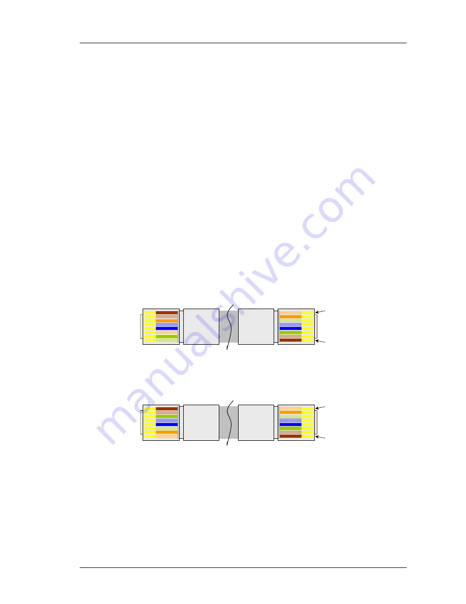
The Ethernet Interface
Pin1
Pin8
1 White/orange
2 Orange
3 White/green
4 White/blue
5 Blue
6 Green
7 White/brown
8 Brown
1 White/green
2 Green
3 White/orange
4 White/blue
5 Blue
6 Orange
7 White/brown
8 Brown
Fig. 9.
View of the cable for connecting the Ethernet port of the TM-81.1 multiplexer
with the MDI-X port of the connected device.
Pin1
Pin8
1 White/orange
2 Orange
3 White/green
4 White/blue
5 Blue
6 Green
7 White/brown
8 Brown
1 White/orange
2 Orange
3 White/green
4 White/blue
5 Blue
6 Green
7 White/brown
8 Brown
Fig. 10.
View of the cable for connecting the Ethernet port of the TM-81.1 multiplexer
with the MDI port of the connected device.
Summary of Contents for TM-81.1
Page 2: ......


