
Concept
Concept Manual
11
continued
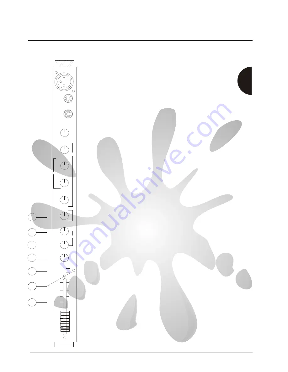
Mic/Line channel
The Mon control is set for pre-fade operation for use as a monitor
send.The signal passes to the feedback filter and monitor fader in
the master section before leaving by the jack socket marked Mon.
Mon
6)
PFL
11)
11)
11
11
GAIN
GAIN
HI
HI
MID
MID
EQ
EQ
+10
+10
+6
+6
0dB
0dB
-6
-6
-10
-10
-20
-20
-30
-30
PEAK
PEAK
PFL
PFL
PAN
PAN
DIGI FX
DIGI FX
AUX 1
AUX 1
FX
FX
MON
MON
LO
LO
GAIN
GAIN
FREQ
FREQ
LINE
LINE
INSERT
INSERT
AUX1
The AUX 1 is set for 'post fade' operation,it traditionaly being used as an
effects send.The signal passes to the Aux 1 master send control before
leaving by the socket marked Aux 1 Output.
The DIGIFX control is a post -fade FX send.It controls the amount of
signal sent to the built in digital effects processor.The signal can then be
DIGI FX
PAN
Assigns (Pans) the channel signal across the left and right master
outputs,the signal being sent equally left and right when set central
Peak
The pre fade listen switch when depressed sends the 'pre fader' channel
signal to the right hand 'bargraph' (VU) display and headphones, allowing
channel 'Gain' to be set and cued. This is non destructive so may be used
at any time during the performance without effecting the main mix output.
The channel fader sets the output level of the channel sent to the
MASTERS . The relationship between the 'fader' and the channel 'gain'
controls is important and this is explained in detail in the setting up
procedure section.
A Peak led is provided which illuminates when the channel level is
approaching clipping.This also illuminates when the PFL switch is enabled
FADER
7
7
6
6
8
8
9
9
10
10
12
12
7)
7)
8)
8)
9)
9)
10)
10)
12)
12)