


Concept
Concept Manual
15
PFL
PFL
+10
+10
+6
+6
0dB
0dB
-6
-6
-10
-10
-20
-20
-30
-30
L R
L R
TAPE
OUT
TAPE
OUT
MON
MON
AUX 1
AUX 1
TAPE OUT
LEVEL
TAPE OUT
LEVEL
AUX 1
MASTER SEND
AUX 1
MASTER SEND
HEADPHONES
HEADPHONES
PFL ACTIVE
PFL ACTIVE
MON TO
LEFT AMP
MON TO
LEFT AMP
FREQ
FREQ
CUT
CUT
MONITOR
MONITOR
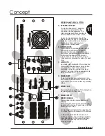
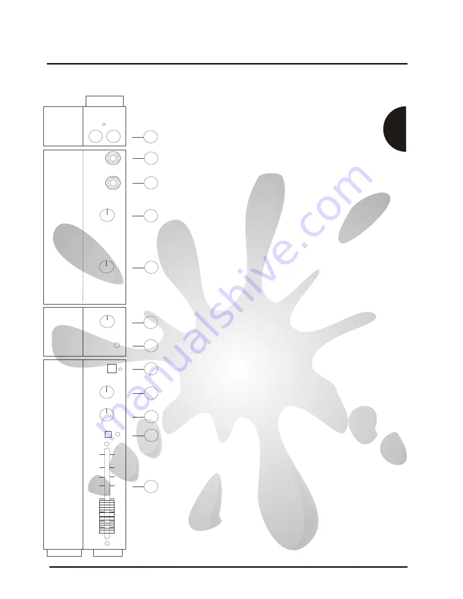
Auxiliary Outputs
TAPE OUTPUT
Controls the signal level at the tape out sockets on the facia and the
line out sockets on the rear.The signal adjusted by this control is the
signal taken from the master mutes i.e. always the L + R Masters.
The Tape Outs are provided for the connection of
Tape/DAT/MD/DCC machines for recording purpose but equaly
could be used for connection to a Hi-Fi amp with Phono /RCA type
connectors
The Line outs are provided for connection of slave amplifiers should
additional speakers need to be connected
Controls the overall signal level at the Aux 1 output.
The signal prior to this level control comes from all the Aux 1
controls on the input channels.The Aux 1 output is a line level
output suitable for connection to external effects processors.Their
outputs normaly being returned via the Stereo Auxiliary.
Adjusts the headphone volume level
The signal on the headphones is the same signal being sent to the
power amplifiers
When PFL is enabled the channel/channels which have been
PFL'ed signal is present on the headphones.
Indicates that a PFL signal is present in the headphones and on the
right meter
Normally the signal to the Power amps comes from the L + R
Masters.If required the Monitor signal can be routed to one of the
left power amps by enabling the Monitor to Left Amp switch.When
the Monitor to Left Amp switch is enabled the Master L + R signal is
summed to together (mono) and is sent to the right power amp.
When this switch is enabled lamps illuminate by the switch and at
the base of the left meter.
Should the Stereo L+R Master be needed when Monitor to Left
Amp is enabled it available at the Line Outs and Tape Out.
The MONITOR signal output.The signal here is a line level output
suitable for connection to an external power amplifier.The signal
level is controlled by the Monitor fader.
These controls form a notch filter for the reduction of feedback on
the monitors. If feedback occurs apply some cut, which should be
swept up and down using the frequency control until the frequency
is found, more cut can be applied to reduce feedback further if
required.
Phono (RCA) sockets are provided for the connection of
tape / DAT machines for recording. The signal level is
controlled by the Line out/Tape out level control.
This is the Aux 1signal output. Signal is sent here by all the
Channel Aux 1 controls .The master control for the Aux 1 output
level is the Aux 1 Master Send Control.The signal level is a line
level signal designed for the connection to external effects
processors
AUXILIARY 1
LINE OUT/TAPE OUTPUT LEVEL
MONITOR
AUXILIARY 1 MASTER SEND
HEADPHONE LEVEL
PFL ACTIVE
MONITOR TO LEFT AMP
FREQUENCY
CUT
27
28
29
30
31
32
33
34
35
36
10
11
27)
28)
29)
30)
31)
32)
33)
34)
35)
36)


