


Concept
Concept Manual
16
Laney
The `EFFECTS' fader controls the level of the
effects signal sent to the Masters.
FADER
The Mon control enables the user to send the
effects signal to the monitor output
PFL
MON
In common with all other inputs PFL facilities are
provided for the setting up of the effects.When
PFL is enabled the signal from the effects unit is
displayed on the right meter and is played in the
headphones
PFL
PFL
8dB
8dB
8dB
8dB
4dB
4dB
0dB
0dB
4dB
4dB
0dB
0dB
-6
-6
-10
-10
-16
-16
-20
-20
-30
-30
-40
-40
0dB
0dB
-6
-6
-10
-10
-16
-16
-20
-20
-30
-30
-40
-40
0dB
0dB
-6
-6
-10
-10
-16
-16
-20
-20
-30
-30
-40
-40
MUTE
MUTE
8dB
8dB
8dB
8dB
4dB
4dB
0dB
0dB
4dB
4dB
4dB
4dB
8dB
8dB
8dB
8dB
4dB
4dB
0dB
0dB
4dB
4dB
8dB
8dB
8dB
8dB
4dB
4dB
0dB
0dB
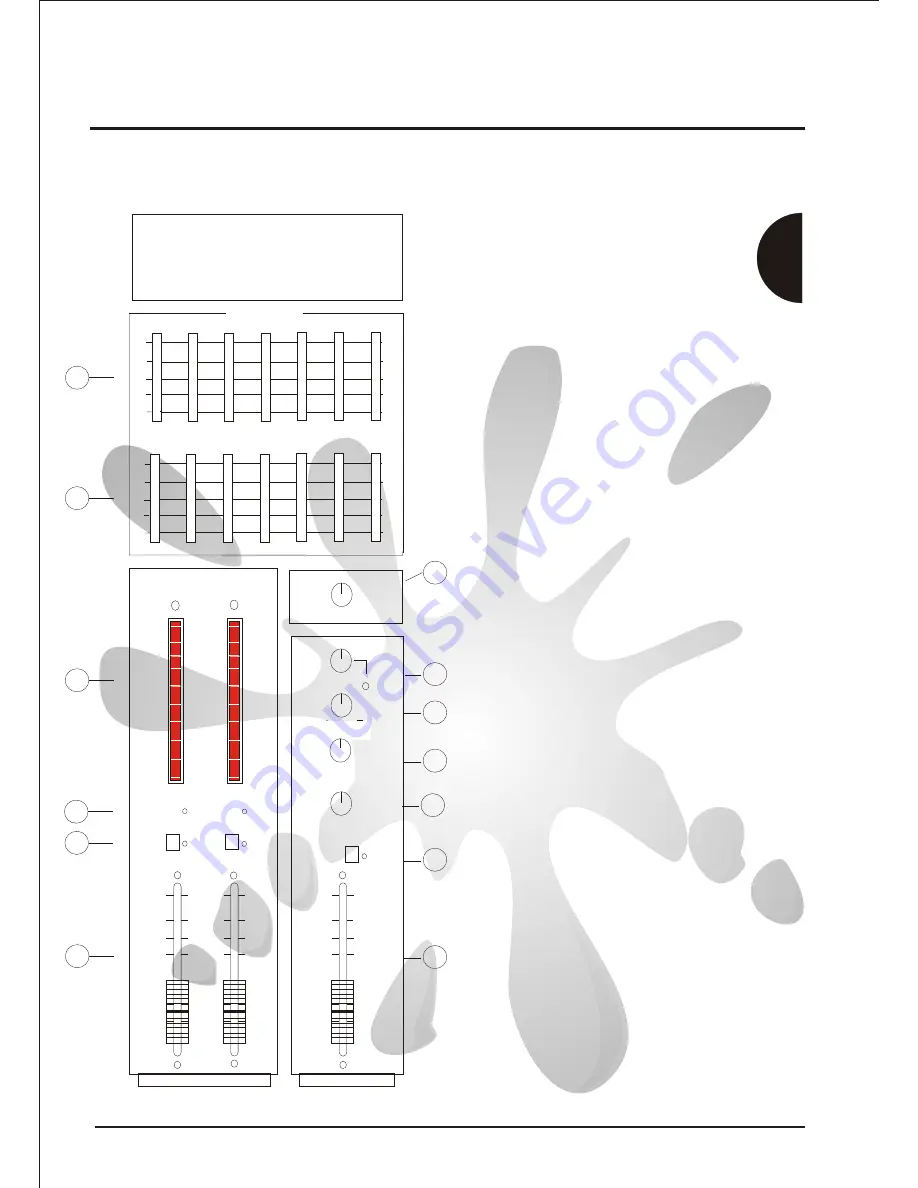
GRAPHIC EQUALISER
GRAPHIC EQUALISER
RIGHT CHANNEL
RIGHT CHANNEL
LEFT / MONITOR
LEFT / MONITOR
ATTENUATION
ATTENUATION
POWER
AMP
LEVEL
POWER
AMP
LEVEL
PEAK
PEAK
INPUT
LEVEL
INPUT
LEVEL
PROGRAM
PROGRAM
MON
MON
LEFT
LEFT
RIGHT
RIGHT
EFFECTS
EFFECTS
+6dB
+6dB
+3dB
+3dB
0dB
0dB
-3dB
-3dB
-6dB
-6dB
-9dB
-9dB
-12dB
-12dB
-15dB
-15dB
-18dB
-18dB
-21dB
-21dB
+6dB
+6dB
+3dB
+3dB
0dB
0dB
-3dB
-3dB
-6dB
-6dB
-9dB
-9dB
-12dB
-12dB
-15dB
-15dB
-18dB
-18dB
-21dB
-21dB
LEFT/
MON
LEFT/
MON
RIGHT/
PFL
RIGHT/
PFL
TIME
TIME
MON ACTIVE
PFL ACTIVE
MASTER MUTES
The 'master meters' show the signal level to the
power amplifiers. The right meter shows RIGHT
or PFL when the PFL switch is enabled. The left
meter shows LEFT or MONITOR when the MON
TO LEFT AMP switch is enabled.
A Graphic Equaliser is provided for fine
tuning of mixes and room acoustics
Centre frequencies are
80Hz,200Hz,430Hz,1.2KHz,2.2KHz,5.5KHz
and 10.5KHz.
Varying the 80Hz / 200Hz filters adjusts
bass frequencies
Varying the 430Hz,1.2KHz and 2.2KHz
adjusts midrange frequencies
Varying the 5.5KHz and 10.5KHz adjusts
treble frequencies
MASTER METERS
GRAPHIC EQUALISER
These turn off the the Master L + R signal. Red
lamps illuminate when muted.
MASTER FADERS
POWER AMP LEVEL
TIME
PROGRAM
INPUT LEVEL
The master faders control the signal level of the
left and right masters before it is routed to the
power amplifiers via mon to left amp
switch,graphic equaliser and power amp level
This is the overall level control for the signal to the
power amps.This provides input sensitivity
matching for external units connected to the insert
loops on the rear panel and increases dynamic
range by reducing residual mix noise.
Typical setting is -6dB.
This controls level of the signal into the built in
Effects processor.This provides the user the ability
to achieve the best signal to noise performance of
the effects unit.
There is peak led near this control to show that the
Effects processor is near clipping.
The above controls allows the selection of 1 of the
127 available programs.These programs are
arranged into 8 types selectable by the `Program'
control. Different program times can then be
selected using the `Time' control.
37
38
38
39
39
40
40
41
41
42
42
43
43
44
44
47
47
45
45
46
46
10
10
48
48
39)
37)
38)
41)
42)
43)
44)
45)
10)
48)
47)
46)


