background image

Concept


Concept Manual 

18

                         
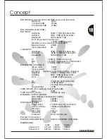
MIX NOISE (measured 22Hz-22K,RMS,power amp level max)
                    Master Up                  -80Bu
                    1 Channel 0dB           -78dBu
                     All channels 0dB       -77dBu

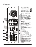
MIC CHANNEL (Fader 0dB )
MIC INPUT:
                    Gain Max.                  60dB + 10dB @ fader buffer
                    Gain Min .                  0dB + 10dB @ fader buffer
                    Bandwidth                  30Hz-20kHz -1dB
                    E.I.N. (Equivalent Input Noise)
                                                       -128dB (150R source Z)
                    Distortion (mic to insets) typicaly <0.007%
                    Maximum input          +20dB
                    Input Impedance        2K
LINE INPUT:
                    Gain Max.                  36dB + 10dB @ fader buffer
                    Gain Min.                   -26dB + 10dB @ fader buffer
                    Bandwidth                  30Hz-20kHz -1dB
EQ:
                    HI                         +12dB @ 12kHz (Shelving)
                    Mid                       +12dB @ Sweepable from 500Hz-5k5
                    Lo                         +16dB @ 80Hz (Shelving)
MIC/STEREO CHANNELS
                    Stereo Gain                 24dB
                    Input overload              >50V
                    Mic Input:     (identical to mic amp on stereo channels)
                    Gain Max.                  +60dB + 10dB @ fader buffer
                    Gain Min.                   0dB + 10dB @ fader buffer
                    E.I.N.                          -128dB (150R source Z)
EQ:
                    HI                               +12dB @ 12kHz (Shelving)
                    Mid                            +12dB @ 2KHz
                    Lo                              +16dB @ 80Hz (Shelving)
                    Faders Buffer            +10dB
TAPE INPUTS (Ref +4dBu @ Output/Fader 0dB)
                    Gain                           15dB
TAPE OUTPUT LEVEL                  Variable by user
MAXIMUM OUTPUT LEVELS
                    Main Outputs (unbalanced) +22dBu
                    Aux Output                 +22dBu
                    Mon Output                +22dBu
POWER AMPLIFIER
                    Power rating              2*300W into 4 Ohms (R.M.S)
                    Hum and Noise         -100dBu (22Hz-22KHz)
                    Distortion                    <0.01
                    Slew Rate                   20V/us
                    Sensitivity                   +4dB
                    Protection                   Short Circuit,Load                                                                                                           
Mismatch,Thermal,D.C.
POWER CONSUMPTION             230V/115V40/60Hz 1000 Watts

DIMENSIONS
                                             width         depth        height
               Concept 10          477mm     449mm     180mm
               Concept 16          627mm     449mm     180mm


Summary of Contents for CONCEPT 10

Page 1: ...Laney Series Mixing Consoles Concept 10 Concept 16 USER MANUAL...

Page 2: ...ept 10 16 Quick Start Diagrams Concept 10 16 Features Mic Line Channel Information Mic Line channel information cont Mic Stereo channel information Auxiliary Output information Auxiliary Input informa...

Page 3: ...sit carton since in the unlikely event that some time in the future your unit should develop a fault you will be able to return it to your dealer for rectification securely packed Your mixer is suppli...

Page 4: ...30 30 PEAK PEAK PFL PFL PAN PAN DIGI FX DIGI FX AUX 1 AUX 1 FX FX MON MON LO LO GAIN GAIN FREQ FREQ MIC MIC GAIN GAIN HI HI MID MID EQ EQ 10 10 6 6 0dB 0dB 6 6 10 10 20 20 30 30 PEAK PEAK PFL PFL PAN...

Page 5: ...changes the input signal this is just like the tone controls on your Hi Fi but with more knobs The controls are labelled Hi Mid gain Frequency and Lo controls 3 It lets you send the signal to places o...

Page 6: ...t by varying amounts A graphic equaliser is provided allowing the overall sound of your mix to be fine tuned Feedback As you set up your mix you will probably have problems with feedback This occurs w...

Page 7: ...volume level be controlled from the your mixer This slave amp could be used for the connection of a subwoofers active loudspeaker or speakers in another room The line outs always have the left and rig...

Page 8: ...INSERT INSERT LINE LINE INSERT INSERT LINE LINE INSERT INSERT LINE LINE INSERT INSERT connect tape DAT machine here for recording connect tape DAT machine here for recording connect tape DAT CD here f...

Page 9: ...OWER CORD BEFORE REMOVING TOP COVER POWER FUSE RATING POWER FUSE RATING 220V 230V 240V T5A 220V 230V 240V T5A 100 120V 100 120V T10A T10A CAUTION REFER TO USER MANUAL BEFORE USING THIS MANUAL CAUTION...

Page 10: ...n this range are cymbals soprano vocals and keys above top C on a keyboard Mid range frequencies can be boosted or cut by this control The frequency of cut is adjustable from approx middle C and up 3...

Page 11: ...l sent to the built in digital effects processor The signal can then be DIGI FX PAN Assigns Pans the channel signal across the left and right master outputs the signal being sent equally left and righ...

Page 12: ...quencies can be boost or cut by this control such as bass guitar kick drums deep vocals and keys below middle C on a keyboard WARNING Phantom power must always be switched off when using unbalanced so...

Page 13: ...listen switch when depressed directs the pre fader channel signal to the right hand bargraph VU display and headphones allowing channel Gain to be set and cued This is non destructive so may be used...

Page 14: ...ape to master PFL monitoring of the tape to master signal is provided A Stereo Auxiliary Input for use as an FX return or as an additional stereo input Stereo signals can be input either on a stereo j...

Page 15: ...and on the right meter Normally the signal to the Power amps comes from the L R Masters If required the Monitor signal can be routed to one of the left power amps by enabling the Monitor to Left Amp s...

Page 16: ...EFT or MONITOR when the MON TO LEFT AMP switch is enabled A Graphic Equaliser is provided for fine tuning of mixes and room acoustics Centre frequencies are 80Hz 200Hz 430Hz 1 2KHz 2 2KHz 5 5KHz and 1...

Page 17: ...S DO NOT OBSTRUCT INLET VENTS MINIMUM LOAD 4 OHMS MINIMUM LOAD 4 OHMS PIN 1GROUND PIN 1GROUND PIN 1 SIGNAL PIN 1 SIGNAL SPEAKER OUTPUTS SPEAKER OUTPUTS RIGHT RIGHT CHANNEL CHANNEL LEFT LEFT CHANNEL CH...

Page 18: ...MIC STEREO CHANNELS Stereo Gain 24dB Input overload 50V Mic Input identical to mic amp on stereo channels Gain Max 60dB 10dB fader buffer Gain Min 0dB 10dB fader buffer E I N 128dB 150R source Z EQ HI...

Page 19: ...Concept Concept Manual FURTHER NOTES...

Reviews: