4: Connecting your guitar to either the 'HI' or 'LO' input has an effect on the sound regardless of the guitar type/pickup
configuration. The 'HI' socket provides more gain and extended treble, but with less bass. The 'LO' socket provides a full
range signal with extended low frequencies and lower gains. You should expermient with both inputs to find the one which
suits your guitar, style of playing and gives you the most tonally pleasing results.
5: When using the 'BRIGHT SWITCH' on an amplifier keep in mind that it has greater audible effect the lower the amount
of distortion produced by the preamplifier. At some distortion levels the 'BRIGHT SWITCH' may appear to have no effect at
all.
USEFUL HINTS AND TIPS
Laney
5
5
LC15 & LC15R manual
VALVE REPLACEMENT AND TROUBLE SHOOTING
The valves in your new valve amplifier will eventually need replacing due to wear, this is normal with valve amps. In most
instances you should be able to effect valve replacement yourself without incurring the costs of a service engineer. Following
are some of the most likely symptoms of valve malfunction and suggested methods of correction.
Normally valve amps give optimum performance when fitted with matched sets of output valves as factory fitted to all Laney
valve amps. NB: Damage will not occur by not fitting matched sets although the amplifiers performance may be impaired.
SYMPTOM
1
Amp connections have been performed correctly but power light fails to illuminate
SOLUTION
1
Check time delay POWER FUSE and replace if necessary
230V Time Delay 250MA
115V Time Delay 500MA
SYMPTOM
2
Power light illuminates - no sound output
SOLUTION
2
Check secondary HT fuse and if blown replace with T100MA
SYMPTOM
3
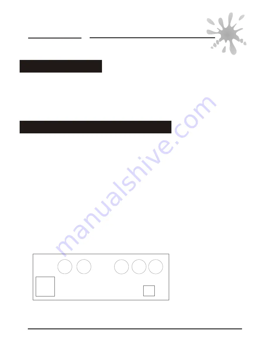
Secondary HT fuse (T100MA) blows repeatedly. This is a strong indication of a damaged output valve. The chart below
shows the valve layout and the function each performs
Laney
LC15 & LC15R manual
V5
V5
V1
V1
V2
V2
V3
V3
V4
V4
V1 = First gain stage, ECC83
V2 = Second gain stage, ECC83
V3 = Phase splitter, ECC83
V4 = Output valve EL84
V5 = Output valve EL84


