background image

8

2M-W1823, Envirozone T

-Stat Electric Griddle

INSTALLATION cont.

Ventilation and Clearances

Standard minimum clearance from combustible construction is as follows.
2” from side
2” from back

These griddles may be set directly, without legs, on a curbed base or 

non-combustible

 surface.

If the griddle is set without legs on a 

non-combustible

 floor or a curbed base, maintain a 4-inch back 

clearance.
Do not install the griddle directly against a 

non-combustible

 back wall or surface.

Do not install the griddle closer than 12 inches from an uncontrolled heat source (char broiler etc.).

Keep the appliance area free and clear of combustible material and do not obstruct the flow of 

combustion or ventilation air.

Electrical Connection

Detach cover on junction box at rear of unit.  There is one power supply connection on the 2, 3, 

and 4-foot griddles.  There are two power supply connections on 5 and 6-foot griddles.  Refer to the 

power supply chart in the Technical Specification Data portion of this manual (pg 4 & 5), for proper 

power supply size.
There is (1) one 1 1/4-inch conduit knockout on 2, 3 and 4-foot griddles located at the rear of the 

griddle, through the back and the bottom of the griddle body. There are (2) two 1 1/4-inch conduit 

knockouts provided on the 5 and 6-foot griddles. Use a supply wire suitable for at least 90°C/194°F.
This griddle is shipped from the factory set up for a three phase service.  On 208V, 220V & 240V the 

wiring can be changed in the supply terminal junction box to convert the griddle to single phase.

Technical Data
Re-Phasing

All griddles are shipped from the 

factory set up for a three-phase 

service. Rearrange the wires in 

the power supply terminal block 

to convert the griddle to single 

phase. Re-phasing the griddle is not 

chargeable to Lang Manufacturing 

Company as warranty. To convert 

to single-phase have a Lang 

Authorized Service Agent, follow 

this chart.

MODEL 

NUMBER

TOTAL 

K.W.

NOMINAL AMPS PER LINE

SINGLE PHASE

THREE PHASE

208 Volt

240 Volt

480 Volt

208V

240V

L1

L2

L3

L1

L2

L3

L1

L2

L3

24”

12

50

28.8

28.8

43.3

25

25

21.7

12.5

12.5

57.7

50

36”

18

50

50

50

43.3

43.3

43.3

21.7

21.7

21.7

86.5

75

48”

24

75

75

50

65

65

43.3

32.5

32.5

21.7

115.5

100

60”

#1

18

50

50

50

43.3

43.3

43.3

21.7

21.7

21.7

86.5

75

#2

12

50

28.8

28.8

43.3

25

25

21.7

12.5

12.5

57.7

50

72”

#1

18

50

50

50

43.3

43.3

43.3

21.7

21.7

21.7

86.5

75

#2

18

50

50

50

43.3

43.3

43.3

21.7

21.7

21.7

86.5

75

PHASING BY WIRE NUMBER

MODEL  

NUMBER

THREE PHASE

SINGLE PHASE

LINE 1 LINE 2

LINE 3

LINE 1

LINE 2

124T

1,4

2

3

1,3

2,4

136T

1,4

2,5

3,6

1,3,5

2,4,6

148T

1,4,7

2,5,8

3,6

1,3,5,7

2,4,6,8

160T #1

1,4

2,5

3,6

1,3,5

2,4,6

160T #2

1,4

2

3

1,3

2,4

172T #1

1,4

2,5

3,6

1,3,5

2,4,6

172T #2

1,4

2,5

3,6

1,3,5

2,4,6

Summary of Contents for 124ZT

Page 1: ...IL2477a ENVIROZONE TSTAT ELECTRIC GRIDDLE Commercial 124ZT 136ZT 148ZT 160ZT 172ZT Installation and Operation Instructions 2M W1823 Rev C 2 11 2015 124ZT...

Page 2: ...OULD BE DONE BY AUTHORIZED SERVICE PERSONNEL ONLY NOTICE Using any part other than genuine Lang factory supplied parts relieves the manufacturer of all liability Lang reserves the right to change spec...

Page 3: ...Crome Surface Griddle Care 12 Troubleshooting Symptoms Possible Causes 13 Possible Causes Test 13 Wiring Diagram 208 240VAC 14 480V 14 Exploded View Parts List 15 20 PROBLEMS QUESTIONS or CONCERNS Be...

Page 4: ...240 60 1 3 18 87 2 50 50 50 6 18 87 2 50 50 50 6 Model Dimensions Not including Legs Clearance from combustible surface Weight Freight Class Width Depth Height Actual Shipping 124ZT 24 61 cm 30 4 77...

Page 5: ...increments Each twelve inch section of the griddle is controlled by an area sensitive RTD probe which can sense and react to a temperature change of 4 F Each twelve inch section has a set of 6 K W ele...

Page 6: ...Prior to un crating move the griddle as near to its intended location as practical The crating will help protect the unit from the physical damage normally associated with moving it through hallways a...

Page 7: ...CAUSE INJURY TO PERSONNEL AND OR DAMAGE TO EQUIPMENT UNIT MUST BE INSTALLED IN ACCORDANCE WITH ALL APPLICABLE CODES NOTICE The data plate is located on the right side of the griddle The grill voltage...

Page 8: ...n the 5 and 6 foot griddles Use a supply wire suitable for at least 90 C 194 F This griddle is shipped from the factory set up for a three phase service On 208V 220V 240V the wiring can be changed in...

Page 9: ...ter the griddle reaches 350 F 176 C for hour turn the griddle up another 50 F 10 C for another hour and repeat this until it is at 450 F 232 C for hour The unit may emit a small amount of smoke as the...

Page 10: ...duct is loaded to the side front or back of the temperature sensor the thermostat will react to the temperature change much slower During slow periods with minimal loads do not load directly over the...

Page 11: ...is an accumulation of burned on grease and food the griddle should be thoroughly scoured and re seasoned Use pumice or griddle stone while the griddle is warm Do not use steel wool because of the dan...

Page 12: ...llowed by wiping with clean wet cloth 3 Follow daily cleaning steps for Non Chrome Surfaces Note All Chrome griddles come with a scrapper p n 2P 50100 15 Bon Ami Cleaner p n 2P 50100 16 and a 20 Palmy...

Page 13: ...OTH HIGH AND LOW VOLTAGES ARE PRESENT INSIDE THIS APPLIANCE WHEN THE UNIT IS PLUGGED WIRED INTO A LIVE RECEPTACLE BEFORE REPLACING ANY PARTS DISCONNECT THE UNIT FROM THE ELECTRIC POWER SUPPLY USE OF A...

Page 14: ...CK 5 PILOT LIGHT 6 5 L3 L2 L1 NOTES 160ZT 172ZT HAVE TWO POWER SUPPLY CONNECTIONS 160ZT CONN 1 USE 136ZT CONN 2 USE 124ZT 172ZT CONN 1 USE 136ZT CONN 2 USE 136ZT 2 3 2 3 2 3 2 3 4 1 1 1 1 148ZT 136ZT...

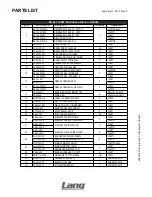
Page 15: ...5 2M W1823 Envirozone T Stat Electric Griddle SK2583 Rev A 6 28 13 Model Electric EnviroZone Griddle 124ZT thru 172ZT 1 2 3 4 7 8 9 11 12 10 27 28 29 26 15 13 14 15 16 17 19 20 21 22 23 24 25 18 5 4 6...

Page 16: ...8 2 KNOB RED METAL INSERT 188 2 Mfg after 6 4 2013 2R W498 KNOB RED Mfg before 6 3 2013 14 2M W728 W4 LABEL CONTROL 200 550F 2 124ZT 15 Y9 31601 01 1 PILOT LT 250V W TIN CLIP 2 124ZT Y9 31601 02 1 PIL...

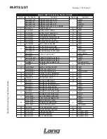
Page 17: ...28 W4 LABEL CONTROL 200 550F 3 136ZT 15 Y9 31601 01 1 PILOT LT 250V W TIN CLIP 3 136ZT 4 136ZTHE Y9 31601 02 1 PILOT LT 480V W TIN CLIP 3 136ZT 480V 136ZTHE 380V 16 K9 60301 43 1 DIE CAST LOGO TINNERM...

Page 18: ...K9 142 251 148ZTD 12 K9 141 161 W1 GREASE DRAWER SLIDE WELD 2 148ZT K9 142 161 W1 148ZTD 13 2R W498 2 KNOB RED METAL INSERT 188 4 Mfg after 6 4 2013 2R W498 KNOB RED Mfg before 6 3 2013 14 2M W728 W4...

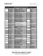
Page 19: ...41 161 W1 GREASE DRAWER SLIDE WELD 160ZT 13 2R W498 2 KNOB RED METAL INSERT 188 5 Mfg after 6 4 2013 2R W498 KNOB RED Mfg before 6 3 2013 14 2M W728 W4 LABEL CONTROL 200 550F 5 160ZT 15 Y9 31601 01 1...

Page 20: ...251 172ZTD 12 K9 141 161 W1 GREASE DRAWER SLIDE WELD 2 172ZT K9 142 161 W1 172ZTD 13 2R W498 2 KNOB RED METAL INSERT 188 6 Mfg after 6 4 2013 2R W498 KNOB RED Mfg before 6 3 2013 14 2M W728 W4 LABEL C...

Reviews: