background image

4


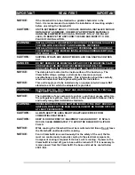
IMPORTANT                            READ FIRST                       IMPORTANT

NOTICE:

If the Clamshell® is to be attached to a griddle/ charbroiler in the
field – it is recommended to complete the installation of mounting adapter
before un-crating the Clamshell®.

CAUTION:

UNIT IS EXTREMELY HEAVY.  FOR SAFE HANDLING, INSTALLER SHOULD
OBTAIN HELP AS NEEDED, OR EMPLOY APPROPRIATE MATERIALS
HANDLING EQUIPMENT (SUCH AS A FORKLIFT, DOLLY, OR PALLET
JACK) TO REMOVE THE UNIT FROM THE SKID AND MOVE IT TO THE
PLACE OF INSTALLATION.

WARNING:

INSTALLATION OF THE UNIT MUST BE DONE BY PERSONNEL QUALIFIED
TO WORK WITH ELECTRICITY AND PLUMBING.  IMPROPER
INSTALLATION CAN CAUSE INJURY TO PERSONNEL AND/OR DAMAGE
TO EQUIPMENT.  UNIT MUST BE INSTALLED IN ACCORDANCE WITH ALL
APPLICABLE CODES.

CAUTION:

SHIPPING STRAPS ARE UNDER TENSION AND CAN SNAP BACK WHEN
CUT.

DANGER:

DO NOT REMOVE THE MOUNTING NUTS OFF OF THE MOUNTING PLATE
STUDS WHILE THE UNIT IS IN THE LOWERED POSITION.  THE
STANCHION BACK IS UNDER TENSION AND CAN CAUSE BODILY INJURY.

NOTICE:

The data plate is located on the inside surface of the hood wrap.  The
Clamshell® voltage, wattage, serial number, clearance and gas
specifications are on the data plate.  This information should be carefully
read and understood before proceeding with the installation.

NOTICE:

This unit is approved to be installed only on equipment which meets NSF
standards, and for which the adapter kit is provided.

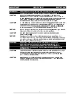
WARNING:

BEFORE LIGHTING, USE A SOAP AND WATER SOLUTION TO TEST ALL
JOINTS FOR GAS LEAKS.

NOTICE:

The installation of any components such as a vent hood, grease extractors,
fire extinguisher systems, must conform to their applicable National, State
and locally recognized installation standards.

WARNING:

DURING INITIAL USE, OR USE AFTER SERVICE, IF THE PILOT DOES NOT
IGNITE ON FIRST TRY THE MAIN GAS VALVE MUST BE TURNED OFF FOR
AT LEAST FIVE MINUTES.

CAUTION:

ALWAYS KEEP THE AREA NEAR THE APPLIANCE FREE FROM
COMBUSTIBLE MATERIALS.

CAUTION:

KEEP FLOOR IN FRONT OF EQUIPMENT CLEAN AND DRY.  IF SPILLS
OCCUR, CLEAN IMMEDIATELY, TO AVOID THE DANGER OF SLIPS OR
FALLS.

NOTICE:

While cooking, the Clamshell® must be monitored at all times. Do not leave
the Clamshell® unattended while cooking.

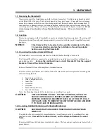
NOTICE:

Fan in Clamshell® runs continuously. For the safety of the unit, the fan
must run continuously to provide cooling to the electrical components.
Component cooling is required if the base unit is running.  If power to the
Clamshell® is turned off, gas to base will be turned off.  If it is necessary to
remove power from the Clamshell®, the base unit must be cooled below
200

°

F first.

Summary of Contents for AGC

Page 1: ...ompany 6500 Merrill Creek Parkway Everett WA 98203 Part Number 60801 Phone 425 349 2400 Fax 425 349 2733 Copyright 1998 WWW LANGWORLD COM Installation Operation Maintenance Troubleshooting Model AGC A...

Page 2: ...LLS GAS THIS INFORMATION SHALL BE OBTAINED BY CONSULTING YOUR LOCAL GAS SUPPLIER AS A MINIMUM TURN OFF THE GAS AND CALL YOUR GAS COMPANY AND YOUR AUTHORIZED SERVICE AGENT EVACUATE ALL PERSONNEL FROM T...

Page 3: ...IRST 4 2 EQUIPMENT DESCRIPTION 6 3 UNPACKING 7 4 INSTALLATION 8 5 INITIAL START UP 10 6 OPERATION 11 7 SEQUENCE OF OPERATION 12 8 CLEANING MAINTENANCE PROCEDURES 13 9 TROUBLESHOOTING 14 10 PARTS LISTS...

Page 4: ...ould be carefully read and understood before proceeding with the installation NOTICE This unit is approved to be installed only on equipment which meets NSF standards and for which the adapter kit is...

Page 5: ...nd direct contact on the tiles can damage them CAUTION DO NOT USE YOUR HAND TO CHECK GRIDDLE CHARBROILER TEMPERATURE NOTICE Service on this or any other LANG appliance must be performed by qualified p...

Page 6: ...nergy and save money with a cooler backroom environment Cook different products at the same time with no height adjustments needed 2 3 Technical Griddle operates on either Natural Gas or Propane This...

Page 7: ...Griddle Charbroiler skip to section 3 4 The Clamshell will arrive completely assembled inside a wood frame covered by a cardboard box and bolted to a skid Remove the cardboard cover unbolt Clamshell...

Page 8: ...the Clamshell itself This connection should be made positioning the manual shut off valve supplied with the Clamshell to isolate the appliance from the kitchens main gas supply during any future serv...

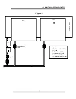
Page 9: ...D Figure 1 Griddle Charbroiler ACV ACV Manual Shut off Valve Regulator Legend ACV Automatic Cut off Valve A 1 Pipe B Reduction to 3 4 Pipe C Reduction to 1 2 Pipe D Increase to 3 4 Pipe O Optional sec...

Page 10: ...g is required if the base unit is running If power to the Clamshell is turned off gas to base will be turned off If it is necessary to remove power from the Clamshell the base unit must be cooled belo...

Page 11: ...tats are provided for temperature control The Clamshell is a radiant cooking device which operates only in the lowered position Ignition is automatic and occurs as the Clamshell is lowered Raising the...

Page 12: ...automatic cutoff valve opens the gas valve to the griddle charbroiler thus allowing the base unit to operate When the Clamshell is lowered the tilt switch allows 24 VAC to go to the spark module The...

Page 13: ...debris from the tiles To clean the Clamshell start with a clean griddle plate Turn off the griddle charbroiler thermostats and wait until the griddle charbroiler is cool CAUTION DO NOT USE YOUR HAND T...

Page 14: ...blower Failed transformer Failed spark electrode Spark but no ignition Failed spark controller Failed gas solenoid valve Clamshell gas valve turned off Plugged orifice Clamshell turns off after exten...

Page 15: ...should be done by a factory authorized service representative Possible Cause TEST Failed tilt switch Unplug switch and test for continuity while raising lowering the hood Failed gas valve Remove the...

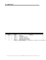
Page 16: ...HOOD WRAP 3 103 193 HOOD SKIRT LEFT SIDE 3 103 194 HOOD SKIRT RIGHT SIDE 3 103 197 HOOD SKIRT FRONT W HINGE 4 50201 08 WIRE GUARD ADD ON BROILER 5 80302 06 IGNITION SENSOR FR 310 5 ref151 26 255 3 0 f...

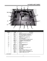
Page 17: ...4 80403 04 90 DEGREE FITTING W 29 DRL NG 80403 05 90 DEGREE FITTING W 44 DRL LP 25 103 64 TUBE 3 26 70101 50 BRAS TBE TEE 3 8 3 8 1 4 27 103 70 TUBE 4 28 80502 03 VALVE SOLENOID GAS 24V 29 AGBS A17 PI...

Page 18: ...18 11 WIRING DIAGRAM...

Page 19: ...ring the warranty period As to warranty service in the territory described above Lang will absorb labor and portal to portal transportation costs time mileage for the first 12 twelve months from the d...

Reviews: