1
INSTALLATION
RECEIVING THE OVEN
Upon receipt of the appliance, check for freight
damage both visible and concealed. Visible
damage should be noted on the freight bill at the
time of delivery and signed by the carrier's
agent. Concealed loss or damage means loss or
damage which does not become apparent until
the merchandise has been unpacked. If
concealed loss or damage is discovered, make a
written request for inspection by the carrier's
agent within 15 days of delivery. All packing
material should be kept for inspection.
Do not
return damaged merchandise to Lang
Manufacturing Company.
File your claim
with the carrier.
Uncrate the appliance as near its intended
location as practical. The crating will help
protect the unit from the physical damage
normally associated with moving it through
hallways and doorways.
DATA PLATE INFORMATION
A data plate is located inside the control
compartment above the control. Look through
the perforated opening above the control panel
and to the left to view the data plate. A
flashlight may be helpful.
The oven voltage, wattage, serial number, wire
size and clearance specifications are on the data
plate.
This information should be carefully read and
understood before proceeding with the
installation.
VENTILATION AND
CLEARANCES
Standard minimum clearance from
combustible
construction is as follows:
2 inches from sides
4 inches from back
6 inches from floor
These ovens may be set directly, without legs, on
a curbed base or
non combustible
floor.
If the oven is set without legs on a
non
combustible
floor or a curbed base, maintain a 4
inch back clearance.
If the oven is set directly against a
non
combustible
back wall, maintain a 6 inch
clearance to the floor.
Do not
install the oven closer than 3 inches from
another oven on the right hand side (control
panel side).
Do not
install the oven closer than 12 inches
from an uncontrolled heat source (char broiler
etc.) on the right side.
Keep the appliance area free and clear of
combustible material and do not obstruct the
flow of combustion or ventilation air.
The installation of any components such as a
vent hood, grease extractors, and/or fire
extinguisher systems, must conform to the their
applicable nationally recognized installation
standards.
LEGS
Legs are available for both the single and double
deck installations. Single deck installations
require a 27 inch leg. Double deck installations
require a 6 inch leg or caster.
To install the 27 inch legs, place cardboard on
the floor and gently tip the oven onto its back.
Fasten two legs to the oven's front corners using
the four 5/16 diameter bolts provided in the leg
kit. Lift the oven onto the front legs and block
the back of the oven using one of the 27 inch
legs set upside down in the center rear of the
oven body. Install the last 27 inch leg onto the
oven body on the control side rear. Gently lift
the oven rear and remove the leg set to support
the oven center and install it on the last rear
corner.
To install the 6 inch legs or casters, attach the
leg/caster to the supports supplied with the oven
(located inside the oven cavity in a box labeled
Leg Pads). Follow the instructions in the Leg
Pad box to attach the pad to the oven.
The adjustable feet on the bottom of each leg
may be screwed in or out as necessary to level
the oven.
Summary of Contents for GCCO-C
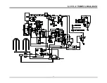
Page 16: ...13 GCCO C WIRING DIAGRAM...


