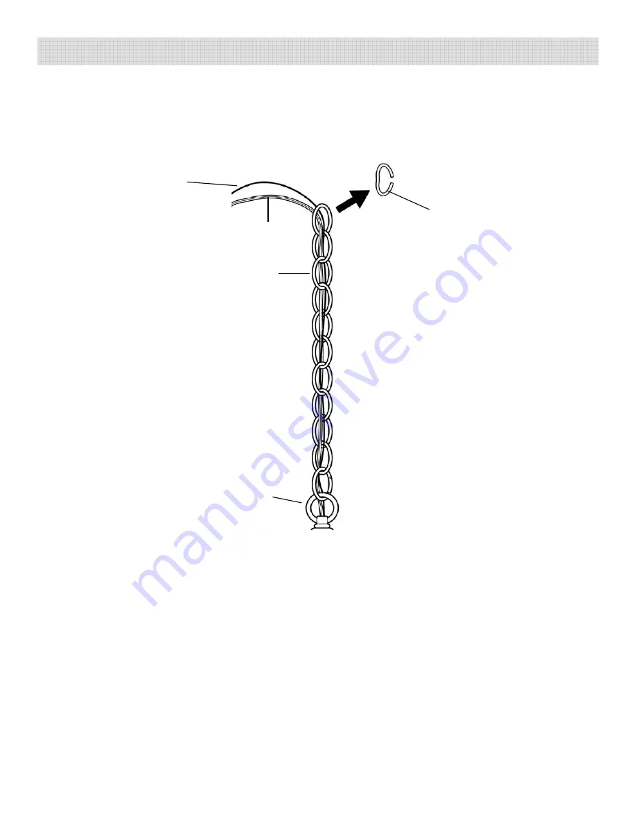
3. Raise the CHAIN and the MAIN FIXTURE BODY up to the OUTLET BOX to determine
the desired length needed for installation.
Identify the chain link that needs to be
opened to remove the excess chain.
Using two pair of pliers, open the chain link.
R
d di
d th
h i
K
th OPENED CHAIN LINK (FIG 2)
ASSEMBLY AND INSTALLATION (CONT.):
OPENED
Remove and discard the excess chain. Keep the OPENED CHAIN LINK. (FIG. 2)
FIXTURE
GROUND
WIRE
CHAIN
LINK
CORD
CHAIN
FIG. 2
TOP
LOOP
4. Thread the two HEX NUTS onto the NIPPLE to its approximate midpoint. Thread the
NIPPLE in throught the center hole of the MOUNTING BRACKET approximately 1/3 of
the way. Do not tighten the HEX NUTS. (FIG. 3)
y
g
(
)
•
Pull the SUPPLY WIRES and the SUPPLY GROUND WIRE out from the OUTLET BOX.
Attach the MOUNTING BRACKET to the OUTLET BOX by feeding the MOUNTING
SCREWS through the slots of the MOUNTING BRACKET and threading them into the
mounting holes of the OUTLET BOX. (FIG. 3)
•
Thread the SCREW COLLAR LOOP 8 or 9 turns onto the bottom end of the NIPPLE.
Tighten the bottom HEX NUT against SCREW COLLAR LOOP (FIG 3)
Page 5
Tighten the bottom HEX NUT against SCREW COLLAR LOOP. (FIG. 3)


