7
wire attaches to the throttle servo arm
with an e-z connector.
5) Slide the horizontal stabilizer in the slot
at the rear of the fuselage. Using your
ruler or measuring tape, center the
stabilizer in the opening. Attach the
wing to the fuselage and block up the
airplane with the wingtips equal
distance from the table. Measure the
stabilizer at the tips. It should measure
the same from each tip to the table. If
the tips are not equal distance from the
table , use sandpaper to sand down the
stab mounting platform until the proper
alignment is achieved. Now measure
from the tip of the stab to the trailing
edge of the wing and adjust the stab
too, so the tips are equal distance from
the trailing edge. Now mark the
stabilizer where it and the fuselage meet
on both side, top and bottom. Now
remove the covering inside of lines.
(Note: Don’t remove the covering up to
the lines. Stay approximately
1/16”inside the lines.)
See the
illustration in the back of the manual
.
Now glue the stab in place using 30-
minute epoxy, rechecking all your
measurements before the epoxy sets.
Set aside to dry. When the epoxy has
cured, run a bead of medium CA as filler
in the gap between the stab and the
fuselage side. Now add the elevator
halves, using the same method used for
hinging the ailerons to the wings.
6) Now install the hinges in the rudder and
trail fit it to the fin. When you are
satisfied with the fit, remove the rudder
and apply 5-minute epoxy to the hole
and slot for the tailwheel wire. When
the epoxy is dry, install the rudder using
same method used for hinging the other
surfaces. Keep the gap as close as
possible while letting the rudder turn
freely.
7) Now slide the tailwheel bracket on the
tailwheel wire up to the fuselage. Using
the bracket as a guide, drill the mounting
holes through the mount. Secure the
bracket with the screws provided.
Install the tailwheel and collar, making
sure the wheel turns freely.
See the
drawing in the back of the manual.
8) Locate the following hardware: 4 nylon
clevises, 4 brass collets, 4 threaded
couplers, 2 control brackets, 2 control
horns, 1 threaded rod, 2 nuts, 2 washers,
and 2 hardwood blocks. Mark & drill a
1/8” hole through the rudder for the
threaded rod, in line with the exit holes
for the rudder cable. Use the nuts and
washers to secure the threaded rod.
Thread a horn bracket on each side of
the rod. Using a pair of wire cutters, cut
the cable into two equal lengths. Install
a coupler at one end of each cable.
9) Insert the cable through the brass collet,
then into the coupler, and back into the
brass collet. Loop it around and back
through the collet again. Squeeze the
collet with pliers and either solder the
assembly with silver solder or apply a
drop or two of thin CA glue.
10) Thread a clevis halfway onto each
coupler and attach the clevises to the
control horns and drop the other end of
the cable into the fuselage theough t he
cable exit holes.
11) Hold the rudder in it’s neutral position
using masking tape. Center the rudder
servo arm. Glue the two hardwood
blocks to the servo tray using medium
CA, to elevate the rudder servo. This
will prevent the rudder servo from
interfering with the other servo arms.
Attach the other two clevises with
couplers to each end of the rudder servo
arm.
12) Now attach the cables to the couplers in
the same manner described above. The
tension should be equal on each side
and the rudder should move freely.
13) Next comes the elevator pushrod.
Mount the two control horns on the
Summary of Contents for Corsair ARF
Page 10: ...10 ...
Page 11: ...LANIER R C 11 ...
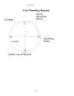
Page 12: ...LANIER R C 12 Cowl Mounting Diagram ...
Page 13: ...LANIER R C 13 F4U Corsair Parts Description ...
Page 14: ...LANIER R C 14 Tail Wheel Assembly ...
Page 17: ...LANIER R C 17 Horizontal Stab Wing Alignment ...
Page 18: ...LANIER R C 18 ...
Page 19: ...LANIER R C 19 ...


