background image

Assembly Instructions

Lanier R/C, INC. P.O. Box 458 Oakwood, Ga. 30566 PH 770 532 6401 © copyright 1989 Lanier R/C

12

12

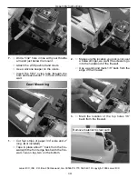
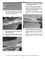
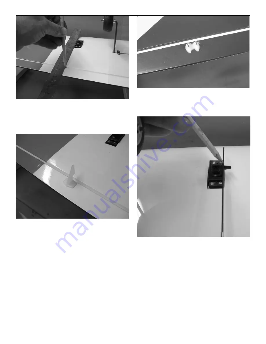
2.

Lay a straight edge along the side of the

aileron servo on the outboard side and

make a mark on the aileron.

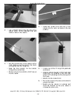
3.

Set the control horn on the aileron at the

mark making sure the holes for the clevis

are aligned over the hinge line. 

Mark the hole location for the screws

through the control horn. 

Remove the horn and drill a 3/32” hole at

the two marks.

4.

Install the control horn with two of the

screws into the nylon nut plate on the top

surface. 

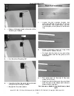
5.

Locate one of the 6” long 2-56 pushrods

and clevis.

Install a silicone keeper on the clevis and

make sure it is screwed on the wire with

about 1/16” extending into the inner part of

the clevis. 

Attach it to the control horn.

6.

Put a servo arm on the servo and center it

using your radio. 

Make sure the aileron is centered and

mark the location on the wire where it

crosses the servo arm.

Summary of Contents for Dart ARF

Page 1: ... We are sure you will be happy with the quality of the kit and happy with the flying characteristics of the Dart Because of it s light weight the Dart will fly exceptionally well on a standard 40 size motor This makes the Dart a perfect first time low wing airplane The gentle flying char acteristics and good aerobatic ability make is a joy to fly ...

Page 2: ...he warranty Lanier R C is proud of the care and attention that goes into the manufacture of parts for its model kits The company warrants that for a period of 90 days it will replace at the buyers request any parts or material shown to the company s satisfaction to have been defec tive in workmanship or material at the time of purchase No other warranty of any kind expressed or implied is made wit...

Page 3: ... the aileron to full deflection in one direction about 1 2 and apply one drop of thin CA glue to each hinge Move the aileron to full deflection in the other direc tion and apply one drop of thin CA on each hinge on that side Give the hinge a minute to dry then apply one more drop to each hinge on each side 2 You will need a 6 extension for the aileron servo lead Use tape on the plug to make sure i...

Page 4: ...rape piece of wood to work the epoxy down into the slots in the wings 6 Slide the dihedral brace into place Slide the other wing in place and use masking tape to hold the wing together till the epoxy cures Check the trailing edge of the wing and use a pin to make sure it stays in perfect alignment Lay the wing down on a flat surface till the epoxy cures don t stand it on one tip This will cause th...

Page 5: ...ng up or down on the stab tip This is all that should be needed but if more is needed you can sand the stab saddle till the alignment is perfect 3 Do the same with the fin When happy with the alignment use a marking pen and mark a line on the stab top and bottom and on both sides of the fuselage Do the same to both sides of the fin 1 With the wing mounted on the fuselage slide the stab into the sl...

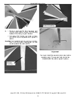
Page 6: ...he lines you just marked Cut about 1 8 inside your mark so bare wood will not be exposed when glued in place Caution Cut carefully and cut only the covering don t cut the balsa underneath as this would weaken the stab and fin remove covering remove covering Important You must install the elevator joiner wire before installing stab The elevator wire cannot be installed after the stab is glued in pl...

Page 7: ... in and the joiner wire fits all the way into the slot 7 When satisfied with the fit put some epoxy in the elevator joiner hole and install the elevators Push the elevators up against the pins then remove the pins and push the eleva tors flush against the trailing edge Flex the elevator to its full travel in one direction about 1 and glue the hinges using thin CA Flex in the other direction and ap...

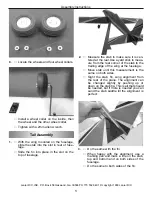
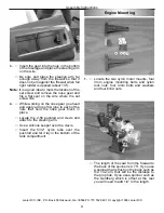
Page 8: ...ear go ahead and apply a drop of CA glue to each of the nuts that hold the nose gear block in place Locate the 2 56 pushrod and clevis and attach to the steering arm Use a silicone keeper over the clevis Insert the 5 32 nylon tube over the pushrod and let it lay in the bottom of the tank compartment Engine Mounting 1 Locate the two nylon motor mounts four 3mm engine mounting bolts and nylon lock n...

Page 9: ...m of the cheek cowls 4 Draw a line down the center of the firewall Measure over 1 8 to the left side of the plane and make another line This will be the offset for right thrust Center you motor mounts on these marks and mark the location of the mounting holes Before drilling the holes check to make sure your muffler will clear the bottom of the fuselage 5 Drill a 13 64 hole at each location This i...

Page 10: ...leave about 1 in front of the fire wall Cowl Mounting 1 Cut four strips of paper 3 4 wide and 2 long Not included Tape in place about 1 back from the fire wall with the front edge flush with the fire wall Two on top two on the bottom 2 Make sure the location you pick is not over a balsa stringer we want the screws to go into the hardwood of the firewall Use a pencil and mark 1 8 back from the edge...

Page 11: ...ttom and sides Pay attention to make sure the cowl is pulled down tight on top and around the cheek cowl and the stripes are aligned 6 When satisfied with the fit drill a 1 16 hole through the marks on the paper tabs into the firewall Make sure to hold the drill square to the firewall Remove the cowl and open the holes up with a 3 32 drill 7 You can use the same method to locate the holes for the ...

Page 12: ...r the screws through the control horn Remove the horn and drill a 3 32 hole at the two marks 4 Install the control horn with two of the screws into the nylon nut plate on the top surface 5 Locate one of the 6 long 2 56 pushrods and clevis Install a silicone keeper on the clevis and make sure it is screwed on the wire with about 1 16 extending into the inner part of the clevis Attach it to the cont...

Page 13: ... wooden dowels two pieces of 2 56 wire 4 long two 12 long 2 56 pushrods two metal clevis two sili cone keepers and 4 pieces of shrink tub ing 2 Make a 90 degree bend 1 4 long in the end of both 4 pieces of wire Fit them into the hole in one end of the wooden dowel and into the groove cut in the dowel 3 Put some glue on the wire in the slot either CA or epoxy Slide the shrink tubing over the wire f...

Page 14: ... Remove the clevis from the pushrods and insert them into the rear of the fuselage and out the holes in the rear Use the pushrod to line up the rudder con trol horn on the right side of the plane Make sure the clevis attachment holes are aligned over the hinge line and mark the location of the mounting holes Drill a 3 32 hole at the mark and mount the control horn using the screws and nut plate 7 ...

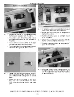
Page 15: ...ors and attach one the the throttle servo arm A three hole arm 1 2 is about right Attach the other connector to the inner most hole on a double sided four hole 3 4 servo arm for the rudder and nose gear 3 Center the rudder servo with the radio and attach the pushrod to the connector Make sure the nose gear is straight and tighten the screw Set the throttle servo to full high motor with the radio 4...

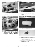
Page 16: ...r Repeat the procedure for the elevator servo Use a four hole out put arm for the elevator 8 Install the switch in the side of the fuse lage on the opposite side from the exhaust Fuel Tank Installation 1 Locate the fuel tank and hardware 2 Assemble the cap with large washer in front and small washer in the rear Bend the long tube at a 45 degree angle so it will reach the top of the tank The fuel p...

Page 17: ...gh the wing opening The tank will sit on the pushrod tubes from the throttle and nose gear Use foam rubber not supplied to cushion the tank Access the front of the tank through the hatch on top and guide the cap assembly into the hole in the firewall Attach fuel line not supplied from the vent line to the muffler pressure tap and from the fuel pick up line to the carb 5 Install hatch using a 2 scr...

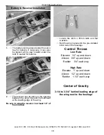
Page 18: ...nd leading edge of the wing next to the fuselage Locate the 4mm x 35mm bolts and flat washers Bolt the wing in place into the pre installed blind nuts in the fuselage 1 The battery can be placed under the servo tray for balance if necessary It can also be placed all the way forward under the tank if needed for balance 2 The receiver can be place in the opening between the servo tray and the bulkhe...

Page 19: ...m x35mm 2 Elevator Rudder Hardware 1 Control horns 2 2 Control horn plates 2 3 Control horn screws Elevator 2x3 4 4 4 2 56x12 control rods with clevis 2 5 Unthreaded pushrods 4 long 2 6 Elevator joiner wire 7 Nylon swing in keepers 4 8 Silicone Clevis keepers 2 9 3 8 wooden dowels 2 10 Shrink tubing 4 11 Adjustable pushrod connector 1 Landing Gear Hardware 1 Main gear mounting straps 4 2 2 screws ...

Page 20: ...icks 13 36 yard stick or tape measure 14 Scissors 15 Moto tool with sanding drum Adhesives 1 Thin CA cyanoacrylate glue 2 Medium CA Glue 3 CA remover debonder 4 5 Minute Zap Z Epoxy 5 30 Minute Zap Z Epoxy 6 Zap Z 42 Thread lock 7 Zap Canopy glue Equipment Required 1 Four channel radio or better 2 Servos 46in oz or better 5 3 650mah battery pack or larger 4 Y connectors 1 5 6 extensions Aileron 2 ...

Reviews: