LANIER R/C
EXPLORER 40
ASSEMBLY
INSTRUCTIONS
14
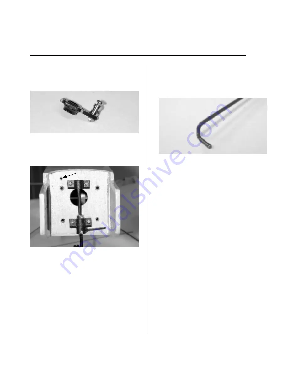
install it on the servo arm. A very small
amount of thin CA will hold the nut in
place.
2. Locate and drill a 5/32” hole, 9/16” on
center and up from the upper engine
mount bolt.
3. Cut off a 11” length of white plastic
sleeving. Push it through the hole
allowing 1/8” to protrude from the firewall
surface. Use thin CA to secure it.
4. Find the length of .050 wire, cutoff
a 17” piece. On one end form a “L” bend
to hook into the throttle arm. Bend a 90
degree leg on the end of the wire. Place
leg in vise with the excess wire parallel
with the vise jaws, allowing a little more
than servo arm thickness between vise
surface and bottom surface of wire. Bend
wire over, with hammer, toward front of
vise. Trim off extending leg to 3/16”.
5. Slide the pushrod in the sleeving and
through the hole in the connector on the
servo arm. Insert the “L” bend into the
throttle arm hole and twist until securely
in place. Throttle adjustment can be
made by powering up the servo, moving
the pushrod back and forth by hand, then
securing it at the servo arm. Temporarily
tighten the set screw on the servo arm
connector until ready for final adjustment.
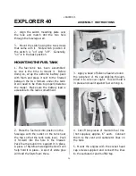
6. The throttle pushrod sleeve must be
supported near the servo. Epoxy in the
balsa support piece as shown in the
photo.
NOSE GEAR PUSHROD
1. The nose gear tiller arm pushrod hook
up is very much like the throttle hook up
using the same materials. Mount the
nose gear assy. Cut off one hole from
the tiller arm, using the second hole.
Move the tiller arm into the firewall and
mark the location for a 5/32” hole.


