background image

                                                       Assembly Instructions

 LANIER R/C

MARINER 40 MK II ARF 

           LANIER R/C, INC.- P O Box 458 - Oakwood, GA  30566 - Ph 770-532-6401 

© Copyright 2006  Lanier R/C, Inc.

11

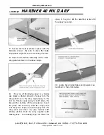
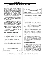
7.  Install the pushrod support on the sleeves 
temporarily for alignment with the servos.  Do 
not glue in place yet. 

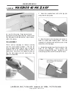
8. Plug the servos into the receiver and 
electrically center them. Mark the position where 
the rod crosses the control arm and make a 90-
degree bend. Cut the leg at 3/8” and attach to 
the servo output arm using the nylon swing in 
keeper. Mechanically adjust the linkage so the 
rudder and elevator are at neutral with the 
servo centered.  Some final adjustment will be 
required later on. 

The pushrod brace can now be glued to the 
bulkhead and the outer sleeves glued to the 
brace.

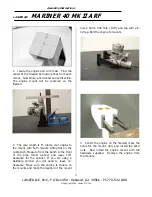
ENGINE MOUNTING 

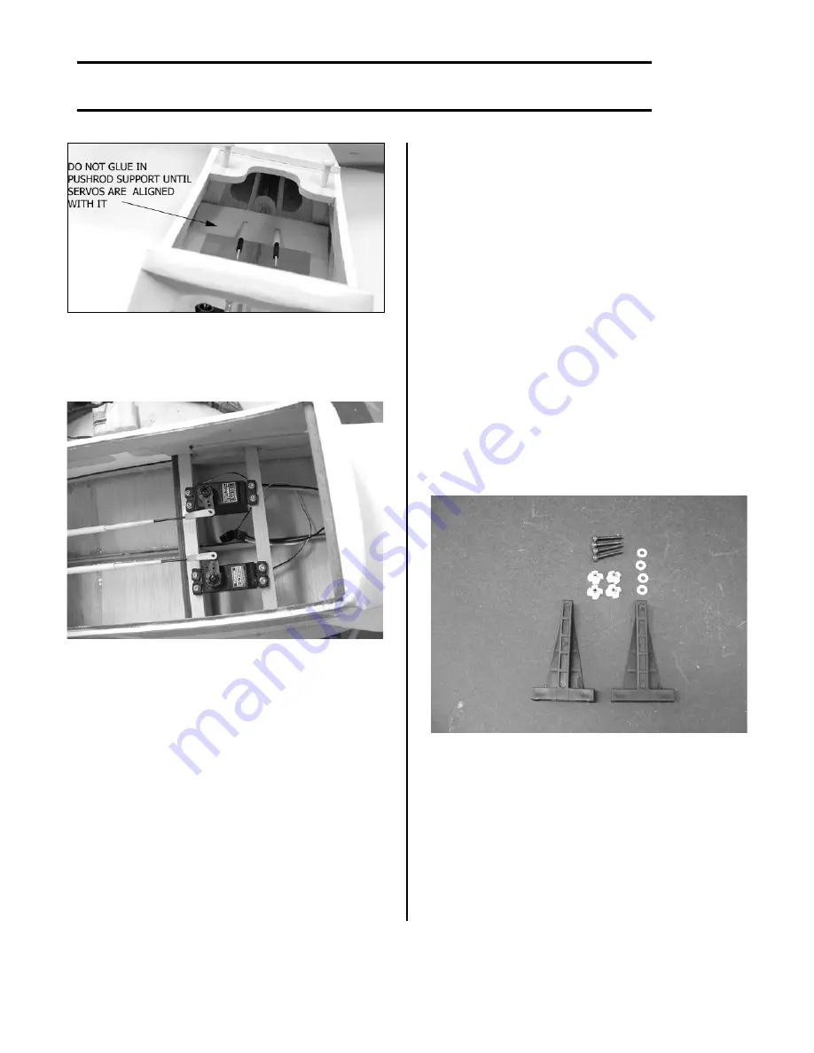
Engine mount and hardware. 

Summary of Contents for MARINER 40 MK II ARF

Page 1: ...de with respect to the merchandise sold by the company The buyer acknowledges and understands that he is purchasing only a component kit from which the buyer will himself construct a finished flying model airplane The company is neither the manufacturer of such a flying model airplane nor a seller of it The buyer hereby assumes the risk and all liability for personal or property damage or injury a...

Page 2: ...ve with an iron Be sure to seal the edges down first so that you do not cause the covering to shrink and leave exposed areas of wood Please inspect the plane before beginning to assemble to make sure you are happy with it After assembly has begun you cannot return the kit If you find a problem before beginning to assemble the plane you must contact us please do not return it to the dealer WING ASS...

Page 3: ...slot Apply a small square of double sticky sided tape not supplied to the servo case to hold it in position Locate 4 pieces of 3 8 x3 4 balsa with 1 8 ply laminated to the top 2 for each servo Epoxy one mount under each servo mounting rail with the plywood next to the mounting lug at each end Be careful not to glue the servo in place When cured install the servo mounting screw not supplied Now do ...

Page 4: ...t up through the hole in the bottom of the wing Tape the end of the lead to the wing to prevent it from falling back into the exit hole Now do the same to the other wing panel Align servo as shown 9 Place the servo board in the wing opening Drill four 1 16 holes in each corner through holes provided Use the 2 x 3 8 screws provided Note hardware may vary in looks from that shown 10 Using a straight...

Page 5: ...all the metal clevis with a lock nut on both ends of the pushrod Install the clevis on the control horn and the servo arm 13 Before pushing the wire through the hole in the float relieve the edge of the hole with a burring tool or 11 X Acto blade so that wire will lay flat against float strut 14 Install the wire strut in the float and fasten in place with the hardware shown in the photo The long l...

Page 6: ... 30 minute epoxy in a mixing cup Apply a liberal amount of epoxy into the wing joiner box in the wing Apply epoxy to the root rib Finally apply epoxy to both sides the top and the bottom of the wing joiner Insert the joiner into the wing Slide the wing panel onto the joiner Wipe any excess epoxy from the wing joint and clean any glue residue with rubbing alcohol Hold the wing together with masking...

Page 7: ...stated before that is with a micro tip soldering iron or by carefully cutting it with a sharp razor Be sure to cut inside the lines so that the bare space will not show when the parts are assembled 1 Draw two parallel lines with a felt tip pen using the slot as a guide 2 Place the stab on the fuselage and center it Hold it in place with masking tape Hold the vertical fin in position and mark the e...

Page 8: ...ou have drawn The fin support also rests against the stab Remove the covering there for wood to wood glue joint The tail components are ready to mount on the fuselage 8 Glue on the stab first using 5 min epoxy Tape a long straightedge on the wing saddle After gluing site from back of fuselage to make sure stab is parallel with the wing 9 Glue on the fin using 5 min epoxy Make sure it is perpendicu...

Page 9: ...he control horn as shown in photo Locate rudder control horn 4 1 4 from bottom edge of rudder Make sure rudder and elevator control horns are on opposite sides 3 Locate the sub dorsal fin Draw a centerline on the bottom of the hull remove the covering the width and length of the fin Install the hinge in the rudder and epoxy the fin in place The rudder and hinge will keep it vertical Tape the forwa...

Page 10: ...2 equal pieces approximately 23 pieces Screw the short threaded rods into one end of the pushrod 1 2 Install the hex nut and screw on a clevis Do two pushrods 4 Prepare the other end of the pushrods that will hook up to the servo arms Locate two 2mm x 6 rods threaded on one ends Screw them in 1 2 on both pushrods 5 Uncover the pushrod exit holes in the aft end of the fuselage Enlarge them so the p...

Page 11: ... receiver and electrically center them Mark the position where the rod crosses the control arm and make a 90 degree bend Cut the leg at 3 8 and attach to the servo output arm using the nylon swing in keeper Mechanically adjust the linkage so the rudder and elevator are at neutral with the servo centered Some final adjustment will be required later on The pushrod brace can now be glued to the bulkh...

Page 12: ...ine to the mount with both mounts sitting flat on the workbench Measure from the bench to the front of the prop thrust washer and leave 1 8 clearance for the spinner If you are using a Goldberg spinner you will need to leave clearance Make sure the engine is square on the mounts and mark the location of the mount holes Drill a 36 hole 106 and tap with a 6 32 tap Bolt the engine to mounts 3 Center ...

Page 13: ...Notch out for mast to allow for cowl adjustment fore and aft if necessary 3 Using a piece of cardboard the height of the pod mark two hole 1 8 in from the front edge and 5 8 from top and 5 8 from bottom Tape it to the pod with the front edge flush with the firewall You will also need one for the other side 4 Slide the cowl on to the pod under the templates Temporarily set the engine in the mount M...

Page 14: ...oles two on each side Use a hand drill however a drill press will ensure straighter holes Do both sides 6 Install four 2 x 3 8 sheet metal screws to retain the cowl in place Fuel Tank Assembly Drill three holes as shown in the photo 1 Locate the fuel tank and assemble the parts on the stopper Bend the vent line carefully to avoid kinking File all sharp corners on tubing ...

Page 15: ...lide the tank in place as shown Feed the lines through the two holes in the firewall 4 Install the throttle servo on the mounts in the pod It may be necessary to shim the servo up so the pushrod will align better with the throttle arm Remove the servo output wheel and assemble an EZ Connector on it Cut a small hole in the bottom of the pod next to the mast to exit the throttle servo connector Tape...

Page 16: ...tape to retain it Now reinstall the engine hook up the throttle linkage and fuel line The engine pod is now complete INSTALLING THE ENGINE POD 1 Locate the mast support Notch off the forward lower edge of the mast to miss possible glue gob at the bulkhead keel joint 2 Trial fit the engine pod assembly to be sure of the fit The mast should be against the bulkhead top and bottom The slot in the bott...

Page 17: ... RH 2 Place them on the hull with the back edge flush with the step Center them on each side While holding in place draw a line around each of them The curved end to the inside 3 Using a sharp Exacto knife cut inside the line remove the covering as shown Use a paper towel and alcohol to remove the ink lines 4 Mix up some 30 min epoxy and glue each lifter in place Make sure you have a good fillet o...

Page 18: ...rtical fin Thus keeping it out of the water Mount the receiver switch inside up close to the wing saddle using the DuBro Kwik Switch and Charging Jack No 207 Coat the pushrod and connector door on the outside of the switch with Vaseline to keep the water out 2 Standard servos may be used They are somewhat water resistant but not water proof Futaba does have a servo that is more water resistant and...

Page 19: ...l clevis are secured with a retainer 3 Make sure the control surfaces move in the proper direction and the throttle is not reversed 4 CHANNEL RADIO SETUP Aileron 3 8 up 3 8 down Elevator 3 4 up 3 4 down Measured at widest part Rudder 1 1 2 left 1 1 2 right Measured at widest part 4 Adjust the pushrod hookups and set up the radio to provide the above control travels Please use the CG location and c...

Page 20: ...dvance the throttle and it will come up on the step with no use of the elevator This is due to the generous spray rails and the special hull lifters mounted on the step The 3 1 2 degrees up thrust in the engine also promotes positive help to accommodate getting up on the step The flight characteristics of the Mariner are very good at all ranges of the flight envelope The full symmetrical wing prom...

Page 21: ...One servo y connector Receiver switch mount DuBro No 207 Fuel line 2 1 4 spinner Tools and Supplies Needed Not Included in Kit Adhesives Thin CA cyanoacrylate glue Medium CA cyanoacrylate glue Thick CA cyanoacrylate glue CA remover debonder 6 minute epoxy 30 minute epoxy Z 42 Threadlock Tools Drill Drill bits 1 16 1 8 5 32 1 4 3 8 Medium Phillips screwdriver Pliers needle nose Small round file Hob...

Reviews: