6
PREPARATIONS
❏
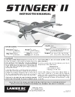
1. If you have not done so already, remove the major
parts of the kit from the box and inspect for damage. If any
parts are damaged or missing, contact Product Support at
the address or telephone number listed in the “Kit Inspection”
section on page 5.
❏
2. Remove the tape and separate all the control surfaces.
Use a covering iron with a covering sock on high heat to
tighten the covering if necessary. Apply pressure over
sheeted areas to
thoroughly
bond the covering to the wood.
ASSEMBLE THE WING
CUT OFF UNUSED ARMS
5/64" [2mm]
13/32"
[10.5mm]
❏
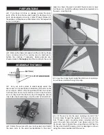
1. Use your radio system to electronically center the
aileron servos. Choose the best orientation of the arms on the
servo outputs shafts so they are parallel with the servo cases.
Cut three arms from a four-armed servo arm for each aileron
servo so they match the photo in step 2. Enlarge the second
inner hole of each remaining arm with a 5/64" [2mm] drill bit.
❏
2. Center the servos with your radio system and install
the servo arms to the servos perpendicular to the servo
cases as shown. Be sure to reinstall the servo arm screws
into the servos. Install the rubber grommets and eyelets onto
the servo mounting tabs.
❏
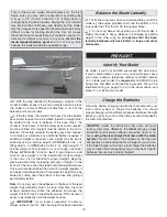
3. Use the strings taped inside the aileron servo openings
to pull the servo leads through the wing.
❏
4. Fit the servos into the servo openings and drill 1/16"
[1.6mm] holes through the eyelets on the servos into the
rails. Thread a servo mounting screw (included with the
servo) into each hole and back it out. Apply a drop of thin
CA to each hole to harden the surrounding wood. When the
CA has dried, install the servos into the openings as shown
using the screws supplied with the servos.
Summary of Contents for MARINER 40 MK II ARF
Page 24: ......


