background image


21

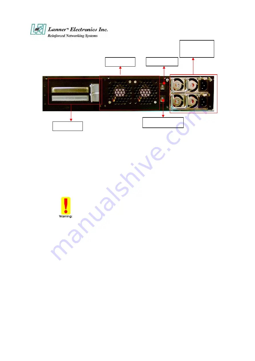
1.5.3 Rear View 


Figure 6 – FW-7890 Rear View 

„


Power Switch:


Click the Power Switch , and the system will be power on. 

„


Power Mute Switch:

  When there is a power supply failure, the system will be alarm. 

Only click the power mute switch and the system will stop to 
alarm. 


Faulty or improper use of the power adaptor may cause permanent damage to the 
power supply and the FW-7890. Plug the adaptor to an electrical wall outlet that 
matches its specifications. 


PCI-X Slot

System Fan

Power Switch

Power Mute Switch

Redundant  
Power Supply 

Summary of Contents for FW-7890 Series

Page 1: ...FW 7890 Series 19 2U Intel Dual Xeron Rackmount Network Security Platform User s Manual...

Page 2: ...mitted in any form or by any means electronic mechanical photocopying recording or otherwise without the formal consent from Lanner Trademark Acknowledgments All products and or brand names stated in...

Page 3: ...st harmful interference when the equipment is operated in a commercial environment This equipment generates uses and can radiate radio frequency energy and if not installed and used in accordance with...

Page 4: ...ject of any kind into this product through openings or empty slots as you may damage parts Do not attach the power supply cabling to building surfaces Do not allow anything to rest on the power cablin...

Page 5: ...is Manual This target audience of this manual includes users administrators and technicians This publication is a useful reference when installing configuring operating and managing the FW 7890 This b...

Page 6: ...Firewall Mechanisms 20 1 5 1 Face Panel 20 1 5 3 Rear View 21 C h a p t e r 2 22 FW 7890 Hardware Installation Guide 22 2 1 Hardware Installation Guide 22 Chapter 3 24 Award BIOS Setup 24 3 1 BIOS Se...

Page 7: ...vii LCD Module and Key Pad For FW 7890 44 A p p e n d i x E 44 LAN Bypass Function 44 Warranty Policy 47 RMA Service 47...

Page 8: ...n DDRII SDRAM DIMM sockets onboard enough for even the most intensive network security applications The FW 7890 is a powerful and flexible unit that can meet the vast and various hardware requirement...

Page 9: ...p to 12 gigabit RJ 45 Connector Storage Two CompactFlash TypeII Socket and Two removable 3 5 Hard Driver Bay via Serial ATA Interface I O Interface One RJ 45 Console port and One USB 2 0 Port Expansio...

Page 10: ...cable RJ 45 x 1 pcs 1 8 meters long cross over Ethernet cable x 1 pcs 1 8 meters long straight through Ethernet cable x 1 pcs Face panel name plate label x 1 pcs Power cable x 2 pcs Drivers and User...

Page 11: ...platform The succeeding sections list all MB X77 related jumper settings and connector pin assignments 1 4 1 Board Layout Figure 3 MB X77 Jumpers and Connectors PCIXA1 FAN3 FAN1 2 PME1 CF1 IDEB1 USBF1...

Page 12: ...Pin 2 54mm Pitch Header FAN 1 3 3 Pin FAN Connector FAN 4 6 3 Pin FAN Connector CF1 Compact Flash Connector COMB1 Serial Port 2 Connector Header LPTA1 Parallel Connector 26 Pin 2 00mm Pitch Header PSC...

Page 13: ...al Speaker PKMB1 PS 2 Keyboard Mouse Connector 2x4 Header 2 54mm PIN NO DESCRIPTION PIN NO DESCRIPTION 1 VCC 2 MSCLK 3 MSDATA 4 KEY 5 KBDATA 6 KEY 7 GND 8 KBCLK CMOS1 Clear CMOS Data CMOS1 Description...

Page 14: ...ta 0 18 Data 15 19 Ground 20 KEY 21 DMA REQ 22 Ground 23 IOW 24 Ground 25 IOR 26 Ground 27 IOCHRDY 28 Ground 29 DMA ACK 30 Ground 31 Interrupt 32 NC 33 SA1 34 PD80P SD80P 35 SA0 36 SA2 37 HDC CS0 38 H...

Page 15: ...3 DATA4 28 DATA12 4 DATA5 29 DATA13 5 DATA6 30 DATA14 6 DATA7 31 DATA15 7 CE1 32 CE2 8 A10 33 VS1 9 OE 34 IOR 10 A9 35 IOW 11 A8 36 WE 12 A7 37 READY 13 CFVCC3 38 CFVCC3 14 A6 39 CSEL 15 A5 40 VS2 16...

Page 16: ...9 Ground 10 KEY LPTA1 Parallel Connector 26 Pin 2 00mm Pitch Header PIN NO DESCRIPTION PIN NO DESCRIPTION 1 Strobe 2 Auto Form Feed 3 Data0 4 Error 5 Data1 6 Initialize 7 Data2 8 Printer Select IN 9 D...

Page 17: ...9 Stand By 5V 21 5V 10 12V 22 5V 11 12V 23 5V 12 3 3V 24 Ground PCIB1 124 Pin Mini PCI Socket Pin No Description Pin No Description 1 TIP 2 RING 3 8PMJ 3 4 8PMJ 1 5 8PMJ 6 6 8PMJ 2 7 8PMJ 7 8 8PMJ 4 9...

Page 18: ...6 AD24 47 AD23 48 IDSEL 49 GROUND 50 GROUND 51 AD21 52 AD22 53 AD19 54 AD20 55 GROUND 56 PAR 57 AD17 58 AD18 59 C_BE 2 60 AD16 61 IRDY 62 GROUND 63 3 3V 64 FRAME 65 CLKRUN 66 TRDY 67 SERR 68 STOP 69 G...

Page 19: ...110 AC_RESET 111 MOD_AUDIO_M 112 RESERVED 113 AUDIO_GND 114 GROUND 115 SYS_AUDIO_OU 116 SYS_AUDIO_IN 117 SYS_AUDIO_OU 118 SYS_AUDIO_IN 119 AUDIO_GND 120 AUDIO_GND 121 RESERVED 122 MPCIACT 123 VCC5VA...

Page 20: ...V 9 PRSNT1 Reserved 10 Reserved 3 3V I O 11 PRSNT2 Reserved 12 CONNECTOR KEY 3 3 volt key 13 CONNECTOR KEY 3 3 volt key 14 Reserved 3 3Vaux 15 Ground RST 16 CLK 3 3V I O 17 Ground GNT 18 REQ Ground 19...

Page 21: ...Reserved 42 SERR Ground 43 3 3V PAR 44 C BE 1 AD 15 45 AD 14 3 3V 46 Ground AD 13 47 AD 12 AD 11 48 AD 10 Ground 49 M66EN AD 09 66MHZ gnd 50 Ground Ground 5 volt key 51 Ground Ground 5 volt key 52 AD...

Page 22: ...AD 57 Ground 73 Ground AD 56 74 AD 55 AD 54 75 AD 53 3 3V I O 76 Ground AD 52 77 AD 51 AD 50 78 AD 49 Ground 79 3 3V I O AD 48 80 AD 47 AD 46 81 AD 45 Ground 82 Ground AD 44 83 AD 43 AD 42 84 AD 41 3...

Page 23: ...in Power Connector Xeon 8P Male Pin No Description Pin No Description 1 Ground 5 12V 2 Ground 6 12V 3 Ground 7 12V 4 Ground 8 12V SATAB1 180 SATA CONNECTOR Pin No Description 1 GND 2 TX_P 3 TX_M 4 GND...

Page 24: ...R1 4 NDCD1 5 NRTS1 6 NRXD1 7 NCTS1 8 NTXD1 9 NRI1 10 NDTR1 11 GENSTS 12 REDSTS 13 HDLED 14 HDLED 15 GND 16 PRLED 17 LCD 18 VCC 19 LPD7 20 LPD6 21 LPD5 22 LPD4 23 LPD3 24 LPD2 25 LPD1 26 LPD0 27 LAFD 2...

Page 25: ...16 SMCLK 17 TRST 18 SMDAT 19 TDO 20 TDI 21 BTX3 22 TMS 23 BTX3 24 BRX3 25 GND 26 BRX3 27 BTX2 28 GND 29 BTX2 30 BRX2 31 GND 32 BRX2 33 BTX1 34 GND 35 BTX1 36 BRX1 37 GND 38 BRX1 39 BTX0 40 GND 41 BTX...

Page 26: ...66 ARX1 67 ATX0 68 ARX1 69 ATX0 70 GND 71 GND 72 ARX0 73 GND 74 ARX0 75 ACLK 76 GND 77 ACLK 78 GND 79 GND 80 PWRGD USBF1 USB Port 1 2 Connector 2x5 Pin 2 54mm PIN DESCRIPTION PIN DESCRIPTION 1 USB_VCC...

Page 27: ...power connected Yellow On Hard disk under access HDD N A Off No Data access Green On When LAN is connected Ethernet Ports Link ACT Orange Flash When Data is accessing Status Lanner Provide the Sample...

Page 28: ...failure the system will be alarm Only click the power mute switch and the system will stop to alarm Faulty or improper use of the power adaptor may cause permanent damage to the power supply and the F...

Page 29: ...in CPU1 System Memory Step 1 The DIMM slot has a notch the DIMM memory module only fit in one direction Step 2 Align the memory notch to the module and push the memory into the DIMM socket Be notes t...

Page 30: ...carefully as shown in the picture Installing the Mini PCI Card Step 1 Insert the PCI expansion card into the mini PCI slot at 45 degree Step 2 Push down the PCI expansion card and the PCI expansion ca...

Page 31: ...ated in one of two ways 1 By pressing Del immediately after switching the system on or 2 By pressing the Del key when the following message appears briefly at the bottom of the screen during the POST...

Page 32: ...ting through the menu bar Use the left and right arrow keys to choose the menu you want to be in To display a sub menu use the arrow keys to move the cursor to the sub menu you want Then press Enter A...

Page 33: ...rated peripherals Power Management Setup Use this menu to specify your settings for power management PnP PCI Configurations This entry appears if your system supports PnP PCI PC Health Status This set...

Page 34: ...se the arrow keys to highlight the item and then use the PgUp or PgDn keys to select the value you want in each item Item Options Description Date Month DD YYYY Set the system date Note that the Day a...

Page 35: ...total memory available in the system IDE Adapters The IDE adapters control the hard disk drive Use a separate sub menu to configure each hard disk drive IDE Primary Master sub menu Use the legend keys...

Page 36: ...default speed boot up sequence keyboard operation shadowing and security Hard Disk Boot Priority Select Hard disk boot device priority Virus Warning The default setting of Virus Warning is Disabled Wh...

Page 37: ...use password feature every time the system boots up The default setting is Setup You can create your password by using the SUPERVISOR USER PASSWORD utility on the main program screen PS 2 Mouse Functi...

Page 38: ...ates EMI Electromagnetic Interference The Spread Spectrum function reduces the EMI generated by modulating the pulses so that the spikes of the pulses are reduced to flatter curves Configuration optio...

Page 39: ...tegrity Mode If you are using the Non ECC DRAM the mode will show Non ECC and this function is disabled ECC Set DRAM mode at ECC Non ECC Set DRAM mode at Non ECC PCI Express A B C Device Select the PC...

Page 40: ...l ATA Port1 Mode are configurable only when the ON Chip Serial ATA item is not set to Disabled Serial ATA Port0 Mode Primary Master Remap SATA Port 0 to IDE Pri Master Primary Slave Remap SATA Port 0...

Page 41: ...he system is powered Configuration options Always Blight DARK 0 1 sec BLINK 0 5 sec BLINK Onboard Serial Port 1 Port 2 Select an address and corresponding interrupt for the first and second serial por...

Page 42: ...gement three of which have fixed mode settings Disable default No power management Disables all four modes Min Power Saving Minimum power management Doze Mode 1 hr Standby Mode 1 hr Suspend Mode 1 hr...

Page 43: ...ed 1 Min 2 Min 3 Min 4 Min 5 Min 6 Min 7 Min 8 Min 9 Min 10 Min 11 Min 12 Min 13 Min 14 Min 15 Min Soft Off by PWR BTTN When set to delay 4 sec the function allows the power button to put the system i...

Page 44: ...perating system can not boot Configuration options Enabled Disabled Resource controlled by The Award Plug and Play BIOS has the capacity to automatically configure all of the boot and Plug and Play co...

Page 45: ...ect CPU temperature automatically System Temperature Detect System temperature automatically FAN 1 FAN 2 FAN 3 Detect Fan1 FAN2 speed status automatically Vcore 1 5V 3 3V 5V 12V 12V 5V 2 6V VBAT Detec...

Page 46: ...he password again and press Enter You may also press Esc to abort the selection and not enter a password To disable a password just press Enter when you are prompted to enter the password A message wi...

Page 47: ...The next time you boot your computer the BIOS configures your system according to the Setup selections stored in CMOS After saving the values the system is restarted again 3 13 Exit Without Saving Pre...

Page 48: ...V 2 32 00 5 1 120mV 5V 0 05 0 70 5 10 1 120mV 12V 0 05 0 70 5 10 1 120Mv 3 3V 1 24 5 1 50mV 5VSB 0 1 2 6 5 1 50mV Feature Active PFC full range MEET IEC 1000 3 2 CLASS D 12V Max Current 32A EMPERATURE...

Page 49: ...hardware that can be used to automatically detect system anomalies and reset the processor if any occur Generally speaking a watchdog timer is based on a counter that counts down from some initial val...

Page 50: ...absent Auto If keyboard is plug in the Controller board the Console Redirection will not display BIOS screen on remote client If keyboard is not plug in the Controller board the Console Redirection w...

Page 51: ...he W2K_WinXP folder LCM SYS Windows 2000 XP Driver LCM REG Windows 2000 XP Registry 1 In Windows 2000 copy LCM SYS to Winnt system32 drivers In Windows XP copy LCM SYS to windwos system32 drivers 2 Do...

Page 52: ...Dp_Type2 int Dp_Type3 int Dp_Type4 char Showdata1 char Showdata2 Show string Function Dp_type1 Entry Mode Set Dp_type2 Display On Off Dp_type3 Shift Dp_type4 Set Function Please refer the Data Sheet...

Page 53: ...ormal state and another is Bypass state Lanner provide three states to enable LAN Bypass function 1 When the system power off it will be forced to enable the LAN Bypass function 2 Customer can enable...

Page 54: ...sulting to the defective goods are excluded from this warranty A Improper or inadequate maintenance by the customer B Unauthorized modification misuse or reversed engineering of the product C Operatio...

Page 55: ...press Others Item Model Name Serial Number Configuration Item Problem Code Failure Status Problem Code 01 D O A 02 Second Time R M A 03 CMOS Data Lost 04 FDC Fail 05 HDC Fail 06 Bad Slot 07 BIOS Probl...

Page 56: ...PEXNSD01 040709 Version 1 0 Printed and published in Taiwan...

Reviews: