background image

Network 

Application Platforms

Hardware platforms for next generation networking infrastructure

FW-8896

V1.3

User's Manual

Release Date: 2016/05/11

Summary of Contents for FW-8896A

Page 1: ...Network Application Platforms Hardware platforms for next generation networking infrastructure FW 8896 V1 3 User s Manual Release Date 2016 05 11...

Page 2: ...tures FW 8896 E F G H 13 Rear Panel Features FW 8896 A B C D 14 Chapter 2 Motherboard Information 15 Block Diagram 15 Motherboard Layout 16 Internal Jumper Connectors 17 Chapter 3 Hardware Setup 21 Pr...

Page 3: ...t Select 53 IntelRCSetup 54 IOAT Configuration 54 Intel R VT for Directed I O VT d Configuration 57 IIO0 Configuration 60 IIO1 Configuration 61 Processor Configuration 62 PCH Configuration 65 PCH SATA...

Page 4: ...Appendix D Programming the LCM 81 Appendix E On Linux 84 Appendix F Terms and Conditions 85 Warranty Policy 85 RMA Service 85...

Page 5: ...s no responsibility for its use nor for any infringements upon the rights of third parties that may result from such use Acknowledgement Intel Atom Pentium Celeron and Xeon are registered trademarks o...

Page 6: ...he room in which you choose to operate your system has adequate air circulation Ensure that the chassis cover is secure The chassis design allows cooling air to circulate effectively An open chassis p...

Page 7: ...dir l quipement une temp rature de fonctionnement acceptable sans circulation adapt e V rifiez que votre site propose une circulation d air ad quate V rifiez que le couvercle du ch ssis est bien fix L...

Page 8: ...0 3 2014 12 10 Updated pin assignments Modified hardware setups Added updated LCM instructions V1 0 2015 06 04 Official release V1 1 2015 07 06 Added BIOS chapter V1 2 2015 12 09 Removed JVGA pinout M...

Page 9: ...rating security packet and compression processes Watchdog Timer and Gen 2 3 LAN Bypass System Specifications Form Factor 2U Rackmount Platform Processor Options 2 x Intel Xeon E5 2600 v3 Series on LGA...

Page 10: ...M802A 8 x GbE SFP Intel i350AM 4 N A NCS2 IXM204A 2 x 10G SFP Intel 82599ES N A NCS2 IXM205A 2 x 10G SFP Intel 82599ES 1 pair NCS2 IXM405A 4 x 10G SFP Intel 82599ESPLX8724 N A NCS2 IXM407 4 x 10G SFP...

Page 11: ...display the operating status with the behaviors as followed If the LED is green it indicates that the system s operational state is normal If it is red it indicates that the system is malfunctioning...

Page 12: ...Rear Panel Features FW 8896 A B C D R1 Low Profile PCIe Expansion Slot R2 4 x Modular Fans R3 Power Switch R4 Power Supply Alarm Switch R5 Redundant Power Supply R3 R1 R2 R5 R4 PSU latch screw PSU LED...

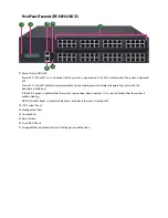
Page 13: ...ting status with the behaviors as followed If the LED is green it indicates that the system s operational state is normal If it is red it indicates that the system is malfunctioning HDD If this LED bl...

Page 14: ...Rear Panel Features FW 8896 A B C D R1 Low Profile PCIe Expansion Slot R2 4 x Modular Fans R3 Power Switch R4 Power Supply Alarm Switch R5 Redundant Power Supply R3 R1 R2 R5 R4 PSU latch screw PSU LED...

Page 15: ...Chapter 2 Motherboard Information Block Diagram The block diagram indicates how data flows among components on the motherboard Please refer to the following figure for your motherboard s layout design...

Page 16: ...e of the pin assignments and the internal connectors CFast1 COMB1 JDDR0 3 MGT1 JFAN2 JDDR12 15 CPU Socket No 1 JVGA1 MGT2 JCOMA1 JOPMA1 J23 JFAN1 JFAN3 JFAN4 ATX3 4 ATX1 2 CPU Socket NO 2 JLCM1 JUSB2...

Page 17: ...wer Connector SATA1 4 SATA Connectors for SATA disk drives Pin Description Pin Description 1 3 3V 2 3 3V 3 3 3V 4 12V 5 Ground 6 Ground 7 5V 8 PSON 9 Ground 10 Ground 11 5V 12 Ground 13 Ground 14 Grou...

Page 18: ...or Pin Description Pin Description 1 2 USB20_L_P2 3 USB20_L_P3 4 USB20_L_N2 5 USB20_L_N3 6 USBGND02 7 USBGND02 8 USB30_TX2P_C_L 9 USB30_TX1P_C_L 10 USB30_TX2N_C_L 11 USB30_TX1N_C_L 12 USBGND02 13 USBG...

Page 19: ...Description Pin Description 1 NDCD1 2 NDSR1 3 NRXD1 4 NRTS1 5 NTXD1 6 NCTS1 7 NDTR1 8 NRI1 9 GND 10 FP_RESET_N Pin Function Pin Function PC1 Tie to Pin17 S1 GND PC2 GND S2 SATA_TX_P0 PC3 S3 SATA_TX_N0...

Page 20: ...N 23 CTR_YEW 24 HDD_LED Pin Description 1 PSU_TTL1 2 PSU_TTL2 3 4 GND 5 6 PMBUS_CLK 7 PMBUS_DAT 8 PMBUS_ALERT Pin Description 1 GND 2 CSOPEN JOPEN2 MGT port SEL IPMI I210 This is the management port f...

Page 21: ...ction gloves to conduct the steps in this chapter Power off the FW 8896 and make sure the power cord 1 is disconnected from the device Loosen the 2 thumbscrews from the rear panel of the 2 FW 8896 Sys...

Page 22: ...em 1 Pull open the DIMM slot latches 2 Align the DIMM module and make sure the notches 3 of the module aligned with the socket keys in the slot Insert the module into the slot until it s firmly seated...

Page 23: ...Press the left load lever down move it out of the retention tab Then do the same to the right There are two levers for each CPU socket 3 Lift the load levers Press down Press down 4 Open the load pla...

Page 24: ...t installed Installing the Disk Drive s Please be noted that FW 8896 series comes with two different HDD SSD designs FW 8896 A B C D is built with one 3 5 HDD SSD slot HDD preferred while the E F G H...

Page 25: ...below 3 The cage of the drive bay will be released The drive bay can be taken out 4 Remove the two screws circled in the image below to remove the slim bar 5 Insert your SATA 2 5 HDD SSD into the tray...

Page 26: ...eps for installation 1 Select a NIC Ethernet module slot 2 Rotate and loosen the two lock screws 3 Remove the door and aim at the PCIe socket for module insertion 4 Insert your NIC Ethernet module Not...

Page 27: ...g preferences Please prepare the power supply units matching this capacity 1 Locate the power supply units 2 Loosen one of the lock screws depending on which power supply unit is to be replaced 3 Hold...

Page 28: ...cing cooling fans 1 Locate the cooling fans at the rear panel 2 Loosen the two lock screws of the fan you would like to replace 3 Hold onto the two lock screws and pull it out 4 Remove the 4 screws th...

Page 29: ...7 Take the worn cooling fan out 8 When using a new cooling fan simply reverse the previous steps to install the fan back onto the enclosure and the system...

Page 30: ...gs should be used when addressing this concern Reliable Earthing Reliable earthing of rack mounted 4 equipment should be maintained Particular attention should be given to supply connections other tha...

Page 31: ...kit does NOT require screw fixing Simply aim at 3 available screw holes on the rack front and lock it by clipping the slide rail assembly to the rack front as shown in the image below You should hear...

Page 32: ...model as far as possible 2 Simultaneously push the release tabs on both sides in the arrow of direction below while pushing the appliance into the end of the rack Caution the appliance will be locked...

Page 33: ...ain screen 4 Instructions of BIOS navigations select a setup screen for instance Main Advanced Chipset Boot Security and Save Exit select an item option on a setup screen Enter select an item option o...

Page 34: ...s screen you may use to select an item you want to configure Above 4G Decoding This option enables or disables 64bit capable devices to be decoded in above 4G address space only if the system supports...

Page 35: ...option enables or disables SRIOV Single Root I O Virtualization support You may select Enable or Disable NCT6776 Super IO Configuration Press Enter to access configuration sub menu for super IO chip...

Page 36: ...O chip for this model is NCT6776 You may select Serial Port 1 2 or Parallet port for configurations Serial Port 1 Configuration Serial Port Once Serial Port 1 is accessed you may press Enter to enable...

Page 37: ...Serial Port 2 Configuration Serial Port Once Serial Port 1 is accessed you may press Enter to enable or disable the Serial Port 1 COMB Device setting is fixed as default...

Page 38: ...rt Configuration This option allows you to set parameters for parallel port LPT LPTE Once Parallel Port 1 is accessed you may press Enter to enable or disable the Parallel Port Device setting is fixed...

Page 39: ...NCT7904D HW Monitor This option allows you to view hardware health status...

Page 40: ......

Page 41: ...re parameters about serial port console redirection Press Enter to access the sub menu Console Redirection select Enabled or Disable for COM port console redirection The default is Enabled Console Red...

Page 42: ...II character set VT100 extends VT100 to support color function keys VT UTF8 uses UTF8 encoding to map Unicode characters onto 1 or more Bits per second select 9600 19200 38400 57600 or 115200 for bits...

Page 43: ...Data Bits select the value for data bits In this case 7 or 8 Parity Bits a parity bit can be sent with the data bits to detect some transmission errors Select None Even Odd Mark or Space...

Page 44: ...unication with slow devices may require more than 1 Flow Control flow control can prevent data loss from buffer overflow When sending data if the receiving buffers are full a stop signal can be sent t...

Page 45: ...es disables VT UTF8 combination key support for ANSI VT100 terminals Recorder Mode on this mode when Enabled only text will be sent This is to capture terminal data Resolution 100 x 31 select Enable o...

Page 46: ...and Key Pad on Putty You may select VT100 LINUX XTERMR6 SCO ESCN or VT400 Redirection After BIOS POST The settings specify if BootLoader is selected than Legacy console redirection is disabled before...

Page 47: ...Configuration Security Device Support This option enables or disables BIOS support for security devices such as TPM module OS will not show Security Device TCG EFI protocol and INT1A interface will n...

Page 48: ...e Version displays USB module version USB Devices displays USB devices Legacy USB Support this function enables or disables legacy USB support Auto option disables legacy support if no USB devices are...

Page 49: ...workaround for operating systems without XHCI hand off support The XHCI ownership change should be claimed by XHCI driver EHCI Hand off this is a workaround for operating systems without EHCI hand off...

Page 50: ...o enable or disable USB mass storage driver The default is Enabled Port 60 64 Emulation this option enables I O port 60h 64h emulation support This should be enabled for the complete USB keyboard lega...

Page 51: ...transfers Device reset time out set USB mass storage device Start Unit command time out 10 20 30 or 40 seconds Device power up delay set the maximum time the device will take before it properly repor...

Page 52: ...s CD ROM AMIVirtual Floppy0 1 00 set mass storage device emulation type Auto enumerates devices according to their media format Please be noted that optical devices will be emulated as CD ROM AMIVirtu...

Page 53: ...LAN Boot Select This option allows you to select one of the onboard LAN boot Press Enter to access the sub menu On Board LAN Boot select Disabled or MGT1 MGT2 management port booting priority...

Page 54: ...ou may use to select an item you want to configure RC Revision displays RC revision information Numa enables or disables Non Uniform Memory Access NUMA IOAT Configuration Press Enter to access the sub...

Page 55: ...ion allows you to enable Intel I O Acceleration Technology which benefits system data flows by reducing CPU overheads The freed CPU resources will improve system responsiveness and avoid performance b...

Page 56: ...Disable TPH TLP Processing Hint disable Relaxed Ordering relaxed ordering enable disable...

Page 57: ...uration This option allows users to configure items of Intel Virtualization Technology for Directed I O VT d Press Enter to access its sub menu VTd AzaleaVCp Optimization this option allows you to ena...

Page 58: ...ected I O VT d enable or disable IntelVirtualizationTechnology for Directed I O VT d by reporting the I O device to VMM through DMAR ACPI tables Interrupt Remapping enable or disable VT d Interrupt Re...

Page 59: ...Coherency Support Non Isoch enable or disable VT d Engine Coherency support Coherency Support Isoch enable or disable Isoch VT d Engine Coherency support...

Page 60: ...nfiguration This function allows users to check PCIe port lane width switch status Press Enter to access the sub menu Set PCIE Port Difurcation By Present Card Lane displays PCIe port information and...

Page 61: ...nfiguration This function allows users to check PCIe port lane width switch status Press Enter to access the sub menu Set PCIE Port Difurcation By Present Card Lane displays PCIe port information and...

Page 62: ...r Configuration This function allows users to view and configure options that can change processor settings Press Enter to access the sub menu Processor Configuration displays processor status and inf...

Page 63: ...ads Execute Disable Bit an Intel hardware based protection against malicious code It will detect the memory in which a code can be executed or not When enabled it will prevent certain classes of malic...

Page 64: ...X2APIC enables or disables extended APIC support AES NI enables or disables AES NI Advanced Encryption Standard New Instruction support...

Page 65: ...PCH Configuration This function allows users to view and configure PCH settings Press Enter to access the sub menu PCH State after G3 select S0 S5 for ACPI state after a G3 The default is Last State...

Page 66: ...PCH SATA Configuration Press Enter to access items for SATA devices and settings SATA Controller enables or disables SATA controller...

Page 67: ...whether the SATA port is connected to a SSD and HDD Select IDE AHCI or RAID The default is AHCI SATA Port 0 displays status of SATA port 0 Software Preserve displays information of Software Preserve P...

Page 68: ...es this port as hot pluggable Spin Up Device if enabled for any of ports Staggered Spin Up will be performed and only the drives which have this option enabled will spin up at boot Otherwise all drive...

Page 69: ...evice Type identifies the SATA port is connected to SSD or HDD SATA Port 1 displays status of SATA port 0 Software Preserve displays information of Software Preserve Port 1 enable or disable this SATA...

Page 70: ...es this port as hot pluggable Spin Up Device if enabled for any of ports Staggered Spin Up will be performed and only the drives which have this option enabled will spin up at boot Otherwise all drive...

Page 71: ...evice Type identifies the SATA port is connected to SSD or HDD SATA Port 2 displays status of SATA port 0 Software Preserve displays information of Software Preserve Port 2 enable or disable this SATA...

Page 72: ...SATA Port 2 DevSlp enable or disable SATA Port 2 DevSlp Device Sleep Board rework for LP needed before enable this option Hot Plug designates this port as hot pluggable...

Page 73: ...erefore SATA port 3 6 all share the same configurable items as desribed for SATA port 0 2 Spin Up Device if enabled for any of ports Staggered Spin Up will be performed and only the drives which have...

Page 74: ...PCH USB Configuration Press Enter to access items for USB configurations xHCI Mode offers modes of operation of xHCI controller You may select Smart Auto Auto Enabled or Disabled...

Page 75: ...gure Administrator Password set administrator password Once set then this only limits access to Setup and is only asked for when entering Setup User Password set user password Once set then this is a...

Page 76: ...s screen you may use to select an item you want to configure Boot Configuration Setup Prompt Timeout number of seconds to wait for setup activation key 65535 0xFFFF means indefinite waitings Bootup Nu...

Page 77: ...option allows you to enable or disable Quiet Boot The default is Disabled based on Intel s server environment setting Boot Option 1 set devices as boot option 1 USB Device BBS Priorities set USB devic...

Page 78: ...nges Save Changes and Reset reset the system after saving the configuration changes Discard Changes and Reset reset the system without saving the configuration changes Save Options Save Changes save t...

Page 79: ...ver and Manual CD Appendix B Setting up Console Redirections Console redirection lets you monitor and configure a system from a remote terminal computer by re directing keyboard input and text output...

Page 80: ...ms Ethernet 3 ports on a host system during three instances Just on Just on is the brief moment when the internal power supply turns on and booting process starts system off or upon software request d...

Page 81: ...m s folder Note The OS supported by Parallel Text based LCM function includes platforms based on Linux Kernel series 2 4 x Linux Kernel series 2 6 x and Linux Kernel series 3 0 x or above Install Inst...

Page 82: ...ay a character on the LCM screen Clean display select Item 5 to clear up the LCM display Leave select Item 6 to exit the program Test This program is a testing script and runs through the following pr...

Page 83: ...plement the virtualization 1 Make sure that the Guest OS has been installed 2 To set up the parallel port pass through please enter VMWare Player s Virtual Machine Setting VMWare Player s setting page...

Page 84: ...r cd e1000 x x x src Compile the driver module by typing the following 5 command make install The binary will be installed as 6 lib modules kernel_version kernel drivers net e1000 o The install locati...

Page 85: ...se The following conditions are excluded from this 5 warranty Improper or inadequate maintenance by the customer Unauthorized modification misuse or reversed engineering of the product Operation outsi...

Reviews: