ICS-I370 User Manual
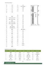
23
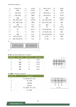
13
NC
14
NC
15
NC
16
LED_WLAN2-
17
NC
18
GND
19
NC
20
NC
21
NC
22
NC
23
NC
32
NC
33
GND
34
NC
35
SW_C_PCIE_TX_P5
36
NC
37
SW_C_PCIE_TX_N5
38
NC
39
GND
40
NC
41
SW_C_PCIE_TX_N5
42
NC
43
SW_C_PCIE_RX_N5
44
NC
45
GND
46
NC
47
CLK_LAN5_DP
48
NC
49
CLK_LAN5_DN
50
NC
51
GND
52
PERST#EKEY
53
NC
54
NC
55
NC
56
NC
57
GND
58
NC
59
NC
60
NC
61
NC
62
NC
63
GND
64
NC
65
NC
66
NC
67
NC
68
NC
69
GND
70
NC
71
NC
72
V3P3_S
73
NC
74
V3P3_S
75
GND
9. J2
: Board to Board Connector
Pin
No.
Description
Pin
No.
Description
Pin
No.
Description
Pin
No.
Description
1
GND
41
GND
2
V3P3_S
42
P1_S0_2
3
GND
43
CTS#2
4
GND
44
LAN34GND
5
USB2_DP4
45
RTS#2
6
USB2_DP3
46
GND
7
USB2_DN4
47
SOUT#2
8
USB2_DN3
48
CTS#3
9
GND
49
SIN#2
10
GND
50
RTS#3
11
PCIE5_TXP
51
GND
12
USB3_TX3_P
52
SOUT#3
Summary of Contents for ICS-I370
Page 13: ...ICS I370 User Manual 13...
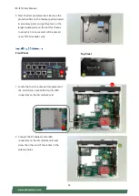
Page 26: ...ICS I370 User Manual 26 4 Lift the cover to remove...
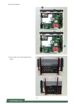
Page 37: ...ICS I370 User Manual 37 3 Then screw on the four antennas to the system A3 A4...
Page 45: ...ICS I370 User Manual 45...
Page 47: ...ICS I370 User Manual 47...
Page 59: ...ICS I370 User Manual 59 Socket 0 CPU Information...
Page 65: ...ICS I370 User Manual 65...
Page 70: ...ICS I370 User Manual 70...


