ICS-I372 User Manual
11
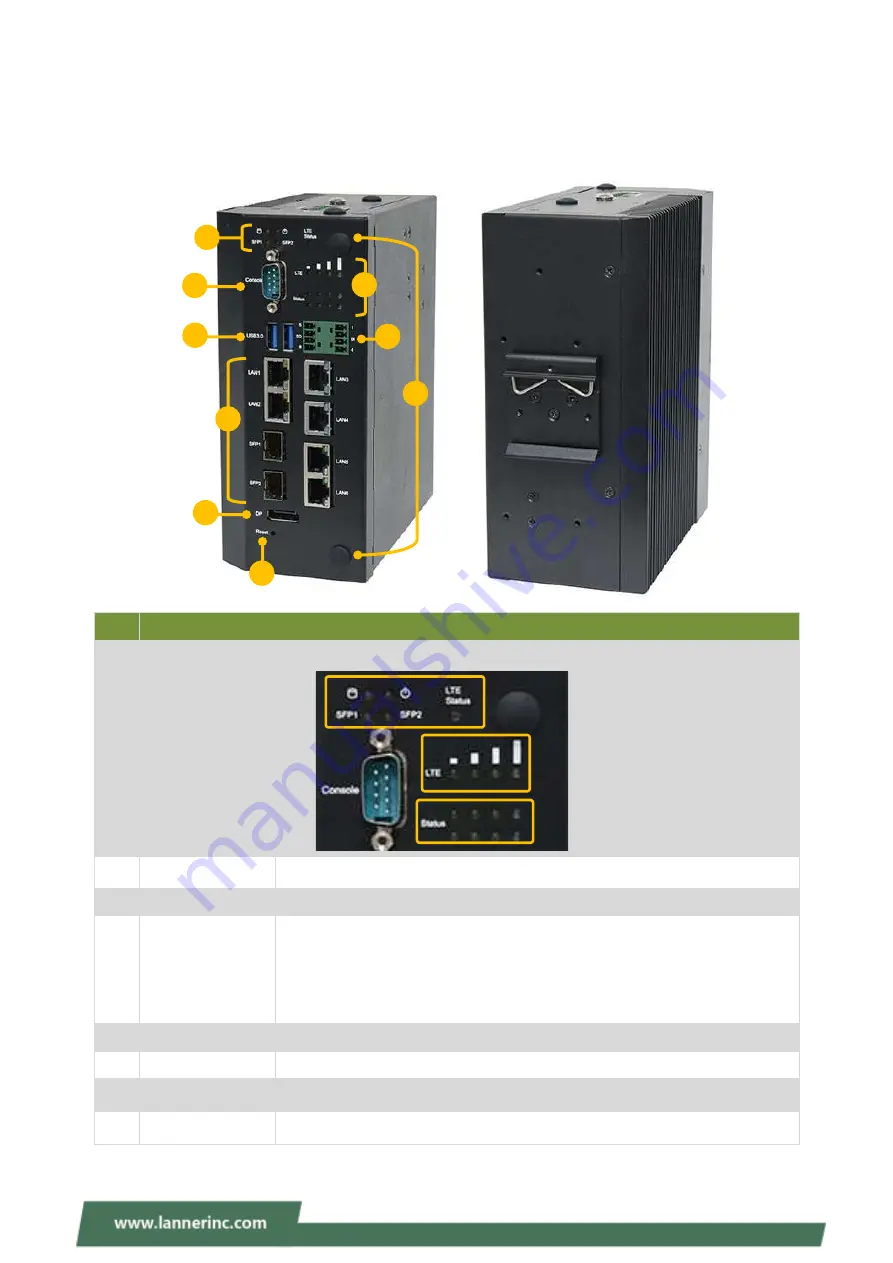
Physical Overview
Front & Rear Panel
Q
No.
Description
F1
LED Indicators
F2
Console Port
1x DB9 Console Port
F3
USB Port
2x USB 3.0 Type A Ports
F4
LAN/SFP Port
SKU A/B: 8x GbE RJ45 (1 or 2 pair bypass) Ports
SKU C/D: 6x GbE RJ45; 2x GbE SFP (1 or 2 pair bypass) Ports
SKU E: 6x GbE RJ45 (one pair bypass) Ports
SKU F: 4x GbE RJ45; 2x GbE SFP (one pair bypass) Ports
F5
Display Port
1x Display Port
F6
Reset Button
1x Reset Button. Use a pin to reset the system
F7
DIO
2x4-pin Terminal block for 2x DI & 2x DO
F8
Antenna
2x Antenna Holes
LED Indicator: Storage Access/Power Status/SFP Status/LTE Status
4x LTE Signal Level Status
F3
F8
F2
2x4 Programmable
F4
F7
F5
F1
F6
F1
Summary of Contents for ICS-I372
Page 13: ...ICS I372 User Manual 13 Motherboard Information Block Diagram...
Page 27: ...ICS I372 User Manual 27 4 Lift the bottom cover chassis to remove...
Page 38: ...ICS I372 User Manual 38 3 Then screw on the four antennas to the system A3 A4...
Page 49: ...ICS I372 User Manual 49 F81966 Super IO Configuration...
Page 56: ...ICS I372 User Manual 56 Hardware Monitor...


