ICS-P570 User Manual
11
Q
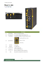
No.
Description
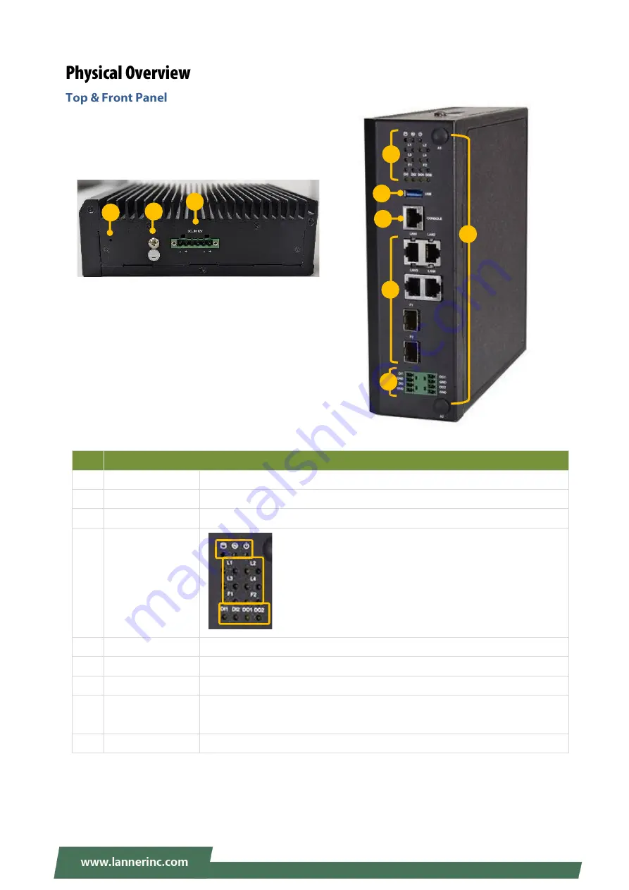
F1
Reset Button
Use a pin to reset the system
F2
Grounding Point For a proper cable to connect the ground
F3
Power Input
1x 6-pin Terminal Block for dual DC input 12~48V
F4
LED Indicators
F5
Antenna
2x Antennas
F6
USB Port
1x USB 3.0 Port
F7
Console Port
1x RJ45 Console Port
F8
LAN/SFP Port
SKU A: 6x GbE RJ45 Ports
SKU B: 4x GbE RJ45 Ports & 2x SFP Ports
F9
DIO
4x2-pin Terminal block for 2x DI & 2x DO
F4
F5
F6
F7
F8
F9
Power/Status/HDD Status (3 LEDs)
LAN Ports (12 LEDs)
DI/DO (4 LEDs)
F1
F2
F3
Summary of Contents for ICS-P570
Page 12: ...ICS P570 User Manual 12 No Description B1 SD SIM Cover SD Card Dual Nano SIM Card Cover B1 ...
Page 13: ...ICS P570 User Manual 13 ...
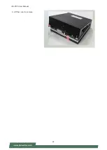
Page 22: ...ICS P570 User Manual 22 4 Lift the cover to remove ...
Page 27: ...ICS P570 User Manual 27 3 Screw the two 2 antennas to the system ...
Page 38: ...ICS P570 User Manual 38 ...
Page 39: ...ICS P570 User Manual 39 ...
Page 40: ...ICS P570 User Manual 40 ...
Page 45: ...ICS P570 User Manual 45 ...
Page 46: ...ICS P570 User Manual 46 Node 0 Information ...
Page 53: ...ICS P570 User Manual 53 ...
Page 54: ...ICS P570 User Manual 54 ...


