ICS-P570 User Manual
26
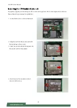
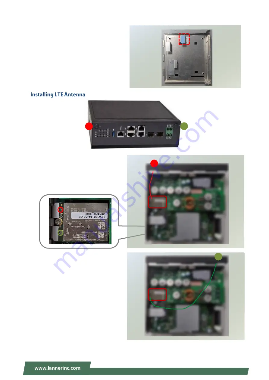
5. Next, thermal pad placement. Remove the
protective film on the two (2) thermal pads
(15x15mm) (included in the accessory pack)
and gently place on the bottom chassis cover.
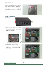
Front Panel
1. Locate the two (2) antenna hole placement
(A1, A2). Locate the two (2) IPEX connectors
on the LTE module card.
2. Connect the RF cables to the IPEX
connectors on the LTE module card and
screw the other end of the cables in the
antenna holes.
A2
ㄉ
A1
A1
A2
ㄉ
Summary of Contents for ICS-P570
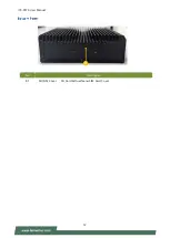
Page 12: ...ICS P570 User Manual 12 No Description B1 SD SIM Cover SD Card Dual Nano SIM Card Cover B1 ...
Page 13: ...ICS P570 User Manual 13 ...
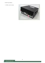
Page 22: ...ICS P570 User Manual 22 4 Lift the cover to remove ...
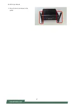
Page 27: ...ICS P570 User Manual 27 3 Screw the two 2 antennas to the system ...
Page 38: ...ICS P570 User Manual 38 ...
Page 39: ...ICS P570 User Manual 39 ...
Page 40: ...ICS P570 User Manual 40 ...
Page 45: ...ICS P570 User Manual 45 ...
Page 46: ...ICS P570 User Manual 46 Node 0 Information ...
Page 53: ...ICS P570 User Manual 53 ...
Page 54: ...ICS P570 User Manual 54 ...

