background image


NCA-1040


User Manual


Version: 1.0 

Date of Release: 2022-04-08 

Network Appliance Platforms 

Summary of Contents for NCA-1040

Page 1: ...1 NCA 1040 User Manual Version 1 0 Date of Release 2022 04 08 Network Appliance Platforms...

Page 2: ...ent font types and icons in order to make selected text more transparent and explicable to users Please note that this document contains the following conventions Example Convention Usage iptables F M...

Page 3: ...customers in the United States and Canada Toll free customer service number 1 855 852 6637 This document is copyrighted 2022 by Lanner Electronics Inc All rights are reserved The original manufacture...

Page 4: ...Town Changping District Beijing 102208 China T 86 010 82795600 F 86 010 62963250 E service ls china com cn USA Lanner Electronics Inc 47790 Westinghouse Drive Fremont CA 94539 T 1 855 852 6637 F 1 510...

Page 5: ...void the user s authority to operate this equipment This transmitter must not be co located or operating in conjunction with any other antenna or transmitter Follow these guidelines to ensure general...

Page 6: ...fectu e par un lectricien form ou une personne form e l lectricit connaissant toutes les sp cifications d installation et d appareil du produit Ne transportez pas l unit en la tenant par le c ble d al...

Page 7: ...ection of the equipment to the supply circuit and the effect that overloading of the circuits might have on overcurrent protection and supply wiring Appropriate consideration of equipment nameplate ra...

Page 8: ...e connexion la terre est tr s importante pour prot ger l quipement contre les effets n fastes du bruit externe et r duire les risques d lectrocution en cas de foudre Pour d sinstaller l quipement d br...

Page 9: ...Panel 14 Jumpers and Connectors 15 Jumper Setting and Connector Pin out 16 Opening the Chassis 23 Installing the System Memory 24 Installing M 2 Memory Card Optional 25 Installing LTE 5G Module Card O...

Page 10: ...NCA 1040 User Manual 10 Save and Exit Menu 55...

Page 11: ...ork Security Platform 1x Power Adaptor 1x Power Cable 1x Console Cable SKU No Main Features NCA 1040A Compact Fanless Network Appliance with Intel Atom x6413E Elkhart Lake 4x Gbe RJ45 1x DDR4 SO DIMM...

Page 12: ...rate 115200 USB 1x USB 3 0 LCD Module N A Display Display Port without Audio Function Power input 1x DC Jack with Lock Antenna Hole 2x Front Antenna holes 2x Rear Antenna holes Storage HDD SSD Suppor...

Page 13: ...iption F1 Antennas 2x SMA Antenna Holes F2 Reset Button 1x Reset Button F3 LED Indicators Power Status Storage M 2 Mini PCIe pls refer to Appendix A F4 Console Port 1x RJ45 Console Port F5 USB Port 1x...

Page 14: ...R2 Power Button 1x Power Button with LED R3 Power Inlet 1x DC Jack with Lock R4 PoE PSE Port 1x 4 pin 54V Input Port with Lock ATX4P for PoE Optional R5 LAN Ports 4x RJ45 Ethernet Ports with LED R6 D...

Page 15: ...NCA 1040 User Manual 15 The following displays the connectors and jumpers on the motherboard layout...

Page 16: ...C_RST J8 Reset Option Pin Description 1 2 Hardware Reset 2 3 Default Software Reset PW2 Power Supply Connector of PSE Pin Description 1 GND 2 GND 3 P54V 4 P54V JPW1 SATA Power Connector 1x4 Pins 2 54m...

Page 17: ...ion 1 P5V_USB1 2 USB20_N1 3 USB20_P1 4 GND 5 USB30_RXN0 6 USB30_RXP0 7 GND 8 USB30_TXN0 9 USB30_TXP0 DP1 Display Port 20P 0 6mm Pin Description Pin Description 1 DP1_C_DATAP0 11 GND 2 GND 12 DP1_C_DAT...

Page 18: ...D 2 TX 3 TX 4 GND 5 RX 6 RX 7 GND PCIE1 MiniPCIe Socket Pin Description Pin Description 1 NC PMC_WAKE 27 GND 2 P3V3_S 28 P1V5_S 3 NC 29 GND 4 GND 30 NC SMB_CLK 5 NC 31 PCIE_TXN 6 P1V5_S 32 NC SMB_DATA...

Page 19: ...in Description Pin Description 1 NC 2 P3V3_S 3 GND 4 P3V3_S 5 GND 6 NC 7 NC 8 NC 9 NC 10 NC 11 GND 12 B KEY 13 B KEY 14 B KEY 15 B KEY 16 B KEY 17 B KEY 18 B KEY 19 B KEY 20 NC 21 NC 22 NC 23 NC 24 NC...

Page 20: ...V3_A 5 GND 6 PH P1V8_A 7 USB2_DP0 8 PH P3V3_A 9 USB2_DN0 10 LED_M2_WWAN_N 11 GND 12 B KEY 13 B KEY 14 B KEY 15 B KEY 16 B KEY 17 B KEY 18 B KEY 19 B KEY 20 PH P1V8_A 21 GND 22 PH P3V3_A 23 NC WAKE_UP...

Page 21: ...NC 59 NC 60 NC 61 NC 62 NC 63 NC 64 NC 65 NC 66 UIM1_DETECT 67 NC M2_RESET 68 NC 69 GND 70 P3V3_A 71 GND 72 P3V3_A 73 GND 74 P3V3_A 75 NC JFAN1 DIP 2 54mm 5 Pin Fan Connector Pin Description 1 GND 2...

Page 22: ..._GPI_2 4 DIO_GPO_2 5 GND 6 GND JSPI1 SMD 2 0mm 2x5 Pin Header Pin Description Pin Description 1 SPI0_IO3_HOLD 2 NC 3 SPI0_CS0_R 4 V_3P3_SPI 5 SPI0_IO1_MISO_R 6 NC 7 NC 8 SPI0_CLK_R 9 GND 10 SPI0_IO0_M...

Page 23: ...r ESD protection gloves when handling the installation steps Pls refer to the Product Unboxing video released by Lanner for reference 1 Power off the system and remove all power connections 2 Turn the...

Page 24: ...stem 2 Turn the system upside down with its bottom side facing up 3 Locate the DIMM socket cover 4 Unscrew the one 1 screw securing the cover And gently lift up the DIMM socket cover 5 Align the notch...

Page 25: ...ow the steps for installation 1 Power off the system and open the chassis cover 2 Locate the M 2 slot on the motherboard 3 Align the notch of the M 2 memory card with the socket key in the pin slot 4...

Page 26: ...nas and 5G module requires four antennas 1 Power off the system and open the chassis cover 2 Locate the M 2 slot on the motherboard 3 Align the notch of the 5G module card with the socket key in the p...

Page 27: ...Manual 27 Installing 5G Antennas Front Panel Rear Panel 1 Locate the four 4 antenna RF cables Locate the four 4 IPEX connectors on the 5G module card 2 Connect RF cables to the 5G module card A1 A1 A...

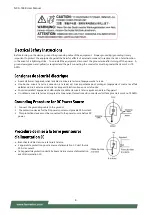
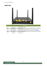
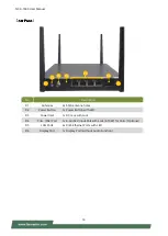
Page 28: ...NCA 1040 User Manual 28 3 Screw on the four 4 antennas to the system A4...

Page 29: ...module requires two antennas 1 Power off the system and open the chassis cover 2 Locate the mPCIe slot on the motherboard 3 Align the notch of the Wi Fi module card with the socket key in the pin slot...

Page 30: ...ling Wi Fi Antennas Rear Panel 1 Locate the two 2 antenna RF cables Locate the two 2 IPEX connectors on the Wi Fi module card 2 Connect the RF cables to the Wi Fi module card 3 Screw on the two 2 ante...

Page 31: ...tem upside down with its bottom side facing up 3 Locate the SIM slot cover 4 Unscrew the one 1 screw securing the cover And gently remove the SIM slot cover 5 Insert and push the nano SIM card all the...

Page 32: ...1 Boot up the system 2 Pressing the Tab or Del key immediately allows you to enter the Setup utility and then you will be directed to the BIOS main screen The instructions for BIOS navigations are as...

Page 33: ...version PI version Project Version BIOS release version Build Date and Time MM DD YYYY Access Level Administrator User FSP Information FSP version Intel FSP binary version RC version Intel reference...

Page 34: ...NCA 1040 User Manual 34 Select the Advanced menu item from the BIOS setup screen to enter the Advanced setup screen Users can select any of the items in the left frame of the screen...

Page 35: ...refetch Enabled Disabled To turn ON OFF prefetching of adjacent cache lines Intel VMX Virtualization Technology Enabled Disabled Intel VMX Virtualization Technology AES Enabled Disabled Enable Disable...

Page 36: ...formance state that the BIOS will set starting from reset vector Intel SpeedStep Enabled Disabled Allows more than two frequency ranges to be supported RC6 Render Standby Enabled Disabled Check to ena...

Page 37: ...NCA 1040 User Manual 37 Feature Options Description Me FW Image Re Flash Enabled Disabled Enable Disable ME FW Update function...

Page 38: ...bles or disables SHA 1 PCR Bank SHA256 PCR Bank Enabled Disabled Enables or disables SHA256 PCR Bank Pending Operation None TPM Clear Schedules an Operation for the Security Device NOTE Your computer...

Page 39: ...NCA 1040 User Manual 39 Feature Options Description Control Legacy PXE Boot From Disabled LAN1 LAN2 LAN3 LAN4 Control PXE Boot from which LAN...

Page 40: ...NCA 1040 User Manual 40 Feature Options Description Serial Port Enabled Disabled Enables or Disables Serial Port 1 Device Settings NA IO 3F8h IRQ 4...

Page 41: ...NCA 1040 User Manual 41...

Page 42: ...NCA 1040 User Manual 42 Feature Options Description Console Redirection Enabled Disabled Enables or Disables Console Redirection...

Page 43: ...Unicode chars onto 1 or more bytes Bits per second 9600 19200 38400 57600 115200 Selects serial port transmission speed The speed must be matched on the other side Long or noisy lines may require low...

Page 44: ...abled Enables VT UTF8 Combination Key Support for ANSI VT100 terminals Recorder Mode Disabled Enabled With this mode enabled only text will be sent This is to capture Terminal data Resolution 100x31 D...

Page 45: ...NCA 1040 User Manual 45 Feature Options Description SR IOV Support Disabled Enabled If the system has SR IOV capable PCIe Devices this option enables or disables Single Root IO Virtualization Support...

Page 46: ...ge should be claimed by XHCI driver USB Mass Storage Driver Support Enabled Disabled Enables or disables USB Mass Storage Driver Support USB transfer time out 1 sec 5 sec 10 sec 20 sec The time out va...

Page 47: ...Enables IPv4 HTTP Boot Support If IPv4 is disabled HTTP boot option will not be created IPv6 PXE Support Disabled Enabled Enables IPv6 PXE Boot Support If IPv6 is disabled PXE boot option will not be...

Page 48: ...NCA 1040 User Manual 48...

Page 49: ...NCA 1040 User Manual 49 Feature Options Description VT d Disable Enable VT d capability Option to Enable Disable VT d X2APIC Opt Out Disable Enable Enable Disable X2APIC_OPT_OUT...

Page 50: ...NCA 1040 User Manual 50 Feature Options Description SATA Controller s Disabled Enabled Enables Disables SATA controller SATA Mode Selection AHCI SATA mode support...

Page 51: ...eft frame of the screen Feature Description Administrator Password If ONLY the Administrator s password is set it only limits access to Setup and is only asked for when entering Setup User Password If...

Page 52: ...oot is activated when Platform Key PK is enrolled System mode is User Deployed and CSM function is disabled Secure Boot Mode Standard Custom Customizable Secure Boot mode In Custom mode Secure Boot Po...

Page 53: ...t keys on next re boot only when System in Setup Mode Restore Factory Keys None Force System to User Mode Configure NVRAM to contain OEM defined factory default Secure Boot keys Enroll Efi Image None...

Page 54: ...he left frame of the screen Feature Options Description Setup Prompt Timeout 5 The number of seconds to wait for setup activation key 65535 means indefinite waiting Bootup NumLock State ON OFF Select...

Page 55: ...ave the changes and exit from BIOS Setup in order for the new system configuration parameters to take effect The following window will appear after selecting the Save Changes and Exit option is select...

Page 56: ...56 Restore Defaults Restore default values for all setup options Select Yes to load Optimized defaults Note The items under Boot Override may not have the same image It would depend on the devices con...

Page 57: ...System is powered OFF Status Green Steady System is Active Red Steady System Error OFF N A System is powered OFF Note Status bi color LED controlled by GPIO Storage Yellow Blinking Storage SATA NVME...

Page 58: ...omer s expense 5 The following conditions are excluded from this warranty Improper or inadequate maintenance by the customer Unauthorized modification misuse or reversed engineering of the product Ope...

Page 59: ...NCA 1040 User Manual 59 When requesting RMA service please fill out the following form Without this form enclosed your RMA cannot be processed...

Reviews: