


NCA-1040 User Manual
57
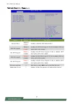
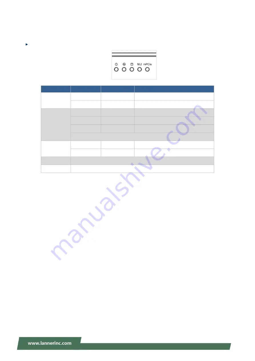
APPENDIX A: LED INDICATOR EXPLANATIONS
Power / Status / Storage / M.2 / mPCIe LED
LED
COLOR
LED ACTION
DESCRIPTION
Power
Green
Steady
System is powered ON
OFF
N/A
System is powered OFF
Status
Green
Steady
System is Active
Red
Steady
System Error
OFF
N/A
System is powered OFF
Note: Status bi-color LED controlled by GPIO
Storage
Yellow
Blinking
Storage (SATA/NVME) Active
OFF
N/A
No Data Access
M.2
LED behavior will be determined by the inserted module card (optional)
mPCIe
LED behavior will be determined by the inserted module card (optional)
Summary of Contents for NCA-1040
Page 1: ...1 NCA 1040 User Manual Version 1 0 Date of Release 2022 04 08 Network Appliance Platforms...
Page 10: ...NCA 1040 User Manual 10 Save and Exit Menu 55...
Page 28: ...NCA 1040 User Manual 28 3 Screw on the four 4 antennas to the system A4...
Page 41: ...NCA 1040 User Manual 41...
Page 48: ...NCA 1040 User Manual 48...


