27
Chapter 5 Console Management
5.1 Connecting to the Console Port
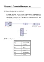
The supplied cable which one end is RS-232 connector and the other end is RJ-45
connector. Attach the end of RS-232 connector to PC or terminal and the other end of
RJ-45 connector to the console port of the switch. The connected terminal or PC must
support the terminal emulation program.
5.2 Pin Assignment
DB9 Connector RJ-45 Connector
NC
1 Orange/White
2
2 Orange
3
3 Green/White
NC
4 Blue
5
5 Blue/White
NC
6 Green
NC
7 Brown/White
NC
8 Brown
Summary of Contents for IPES-3408GSFP
Page 6: ...3 Stability Testing IEC60068 2 32 Free fall IEC60068 2 27 Shock IEC60068 2 6 Vibration...
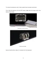
Page 23: ...20 LC connector to the transceiver...
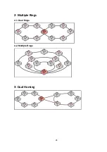
Page 27: ...24 2 Multiple Rings 2 1 Dual Rings 2 2 Multiple Rings 3 Dual Homing...
Page 29: ...26 4 5 Chain in Chain...
Page 58: ...55 Demo Demo display each topology in different application...
Page 91: ...88 6 16 1 8 The setting of neighbour switch 6 16 1 9 The setting of none switch...
Page 96: ...93 ARP Table You can find the MAC addrees of each IP you have ping via this switch in here...
Page 100: ...97 Straight through cables schematic Cross over cables schematic...
Page 119: ...116...


