Hardware Interfaces
BOLERO40 Series Hardware Manual
30
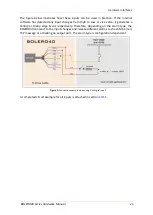
Figure 7:
1-Wire typical application
More details about the 1-Wire interface refer to the document
"AppNote_1-
Wire_Guide.pdf"
.
6.2
Inserting a SIM card into the SIM holder
BOLERO40 has a GSM modem that requires a SIM card to access to the mobile network
services. The SIM card is obtained from your mobile provider and must be activated for
GSM data services before using it. Together with the SIM card, you receive a 4-digit PIN
number. Entering of the PIN allows your device to access the mobile network.
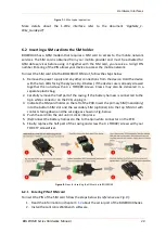
To insert the SIM card into the BOLERO40' SIM slot, follow the steps below:
1.
Remove the power supply and any other connections from the device. Hold the device
with the two LEDs facing the sky (see
Fig. 8
below). If the device case is already screwed
together then unscrew the 4 x TORX#8 screws. Crews may also be delivered in a
separate plastic bag.
2.
Carefully remove the half part of the casing. If the battery harness is connected to the
3pin white connector on the PCB, unplug it.
3.
Indicate the SIM card holder on the left of the PCB. Insert the primary SIM (mandatory)
into the bottom SIM slot and the secondary SIM (optional) into the top SIM slot with
contacts facing down and the cat edge as shown in Fig. below.
4.
Push the card into the slot until it clicks into place.
5.
(Re)Connect the battery harness to the to the 3pin white connector on the PCB.
6.
Finally, replace the half part of the casing and screw the 4 x TORX#/ screws with your
TORX T7 screwdriver.
Figure 8
: Steps for inserting the SIM card into BOLERO40
6.2.1
Entering PIN of SIM card
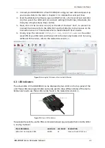
To insert the PIN of the SIM card follow the steps below
(as reference use Fig. 9)
:
1.
Read the information in chapter
about the serial port of the BOLERO40 Series.
2.
Install the Lantronix Workbench software,


