4: Installation of EDS4100
EDS User Guide
30
LED on the back of the EDS4100 shows the connection of the attached Ethernet
network. The EDS4100 can be configured to operate at a fixed Ethernet speed and
duplex mode (half- or full-duplex) or auto-negotiate the connection to the Ethernet
network.
Terminal Block Connector
The back of the EDS4100 has a socket for a terminal block screw connector (not
included) for attaching to an appropriate power source, such as those used in
automation and manufacturing industries. The terminal block connector supports a
power range from 42 VDC to 56 VDC. It can be used with the EDS4100’s barrel
power connector and PoE capabilities as a redundant power source to the unit.
Vendors who do supply this connector can be found by doing a web search for part
‘Phoenix 1803581 MC 1,5/ 3-ST-3,81’.
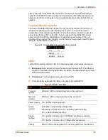
Figure 4-5. Terminal Block Connector Pin Assignments
Pin
Signal
Top
V+
Middle
V-
Bottom
Ground
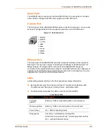
LEDs
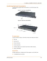
Light-emitting diodes (LEDs) on the front and back panels show status information.
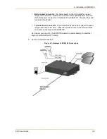
Back panel. Each serial port has a Transmit and a Receive LED. The Ethernet
connector has Speed and Activity LEDs. In addition, the back panel has a Power
LED and a Status LED.
Front panel. The front panel has a green Power LED.
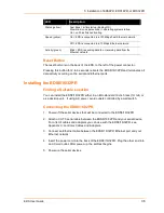
The table below describes the LEDs on the back of the EDS4100.
Figure 4-6. Back Panel LEDs
LED
Description
Transmit
(green)
Blinking = EDS is transmitting data on the serial port.
Receive
(yellow)
Blinking = EDS is receiving data on the serial port.
Power (green)
On = EDS is receiving power.
Status
(yellow)
Fast blink = initial startup (loading OS).
Slow blink (once per second) = operating system startup.
On = unit has finished booting.
On = EDS is connected to a 100 Mbps Fast Ethernet network.
Speed
(yellow)
Off = EDS is connected to a 10 Mbps Ethernet network.
Activity
Blink = EDS is sending data to or receiving data from the Ethernet

