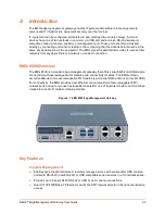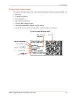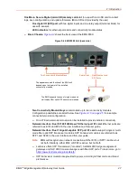
2: Introduction
EMG™ Edge Management Gateway User Guide
26
Hardware Components
EMG Chassis:
The EMG has a 1U-tall (1.75 inch),
212.6mm [8.37”] L x 167.68mm [6.60”] W
x 43.21mm [1.70”]
H chassis. Options for rack mounting and wall mounting are available.
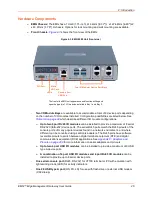
Front Chassis:
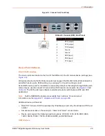
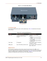
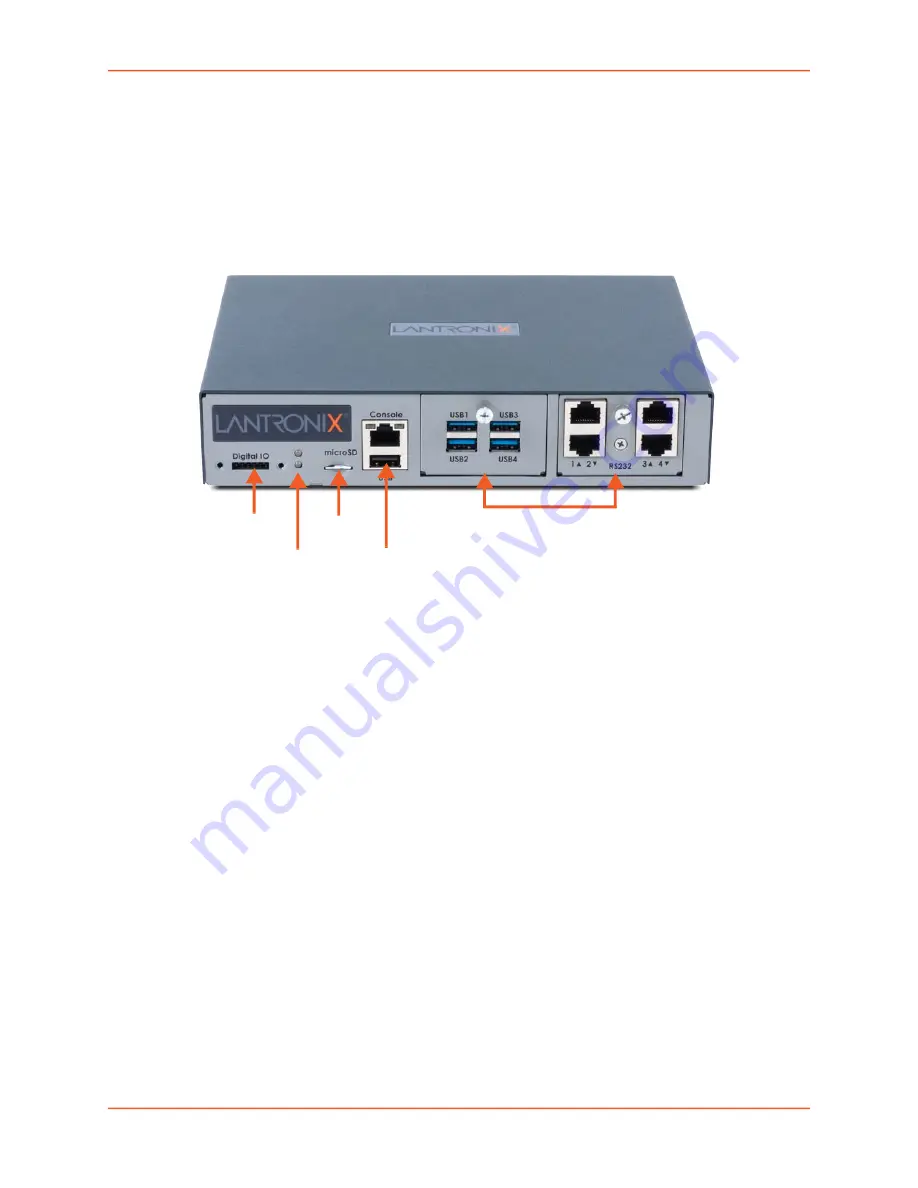
shows the front view of the EMG:
Figure 2-3 EMG 8500 Unit (front side)
-
Two I/O Module Bays
are available to accommodate a total of 8 device ports depending
on the number of I/O modules installed. Configuration possibilities are listed below. See
which describes different I/O module configurations.
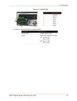
Up to two 4 port RJ45 I/O modules
can be installed to provide a maximum of 8 serial
RS-232C (EIA-232) device ports. The serial RJ45 ports match the RJ45 pinouts of the
console ports of many popular devices found in a network environment, and where
different can be converted using Lantronix adapters. The RJ45 ports have software
reversible pinouts to switch between digital terminal equipment (DTE) and digital
communications equipment (DCE) applications. See
for more information on serial adapters and pin-outs.
Up to two 4 port USB I/O modules
can be installed to provide a maximum of 8 USB
type A device ports.
A combination of 4 port USB I/O modules and 4 port RJ45 I/O modules
can be
installed to provide up to 8 serial device ports.
-
One serial console port
(RJ45, RS-232) for VT100 terminal or PC with emulation with
light emitting diode (LED) for activity indicators
-
One 2.0 USB type A port
(HS, FS, LS) for use with flash drive or external USB modem
(V.92 dialup)
DIO Port
Micro
SD Card
LEDs
Console Port
USB Port
The front of the EMG unit appearance and function will depend
upon the type(s) of I/O modules installed in Bay 1 and Bay 2.
Two I/O Modular Device Port Bays


